Determining Filter Parameters for the Composite Receiver – Appropriate Filter Rejection Requirements
VNAs using the cold source noise figure measurement technique need to filter out potential signals that may be present that would distort the measurement. Common examples are the LO harmonics located in the VNA. Following is a procedure for determining potential LO harmonics that should be filtered in VectorStar.
• Generally one should aim for ~ > 15 dB of rejection at the offending frequency(ies). ~ 20 dB to –25 dB may be needed if the gain profile is peaking at the offending frequency.
• For NF measurements below 2.5 GHz, just a 2.5 GHz LPF should be adequate.
• For NF measurements from 2.5 GHz to 70 GHz, it is a three step process (unless the measurement range spans multipliers – in which case the measurement may need to be broken into segments).
Procedure 1 – Frequencies From 2.5 GHz to 70 GHz
1. Use the table below to determine the multiplier that will be needed to reach the measurement frequencies:
Frequency Range (GHz)
Multiplier
2.5 to 5
x1 (Watch out for the harmonic)
5 to 10
x1
10 to 20
x2
20 to 40
x4
40 to 70
x8
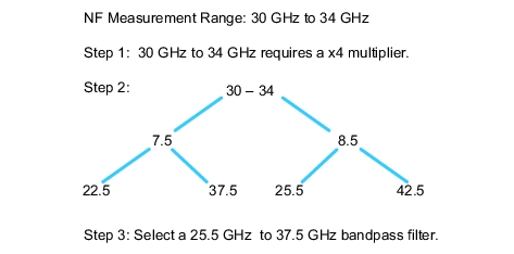
2. Take the lowest NF measurement frequency and divide by the multiplier. Take that number and multiply it by the next lowest and highest integer. Repeat the process with the highest NF measurement frequency.
3. Select a filter that avoids these harmonics you calculated above.
Note
If the amplifiers used in the composite receiver are band-limited, they may provide some natural filtering on their own.
Example 1
Procedure 2 – Frequencies Above 70 GHz
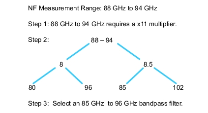
For frequencies above 70 GHz or for which the 3744A-Rx receiver is being used, it is a similar set of steps with the following multipliers:
1. Use the table below to determine the multiplier that will be needed to reach the measurement frequencies:
Frequency Range (GHz)
Multiplier
54 to 80
x9
80 to 110
x11
10 to 125
x13
Example 2
Ensuring Noise Figure Measurement is in Proper Noise Figure Measurement Range
In general, the user should target a noise power 5 dB to 10 dB below the receiver 0.1 dB compression point and above ~ –140 dBm. This is the power level going into the b2 receiver with the composite receiver in place. It should be measured after doing the receiver cal, but with no DUT connected.
Generally, the receiver gain + DUT gain should be between ~ 40 dB and 70 dB for linearity optimization. For composite receiver amps, lower receiver noise figures are better. But if the DUT gain exceeds ~ 10 dB, it does not matter much. A small pad on the input (1 dB to 2 dB) can reduce receiver noise parameter sensitivity if the DUT amp happens to be sensitive to source impedance; this is not typical.
When might an amplifier DUT need improved source match?
If the measured DUT NF has spikes (~ > 5 dB), checking the sensitivity of the composite receiver to the load it sees may be helpful. This check is done after the receiver cal and the noise cal have been completed. To check, users can add a small pad on the input of the composite receiver and measure the noise power (leaving the pad non-terminated/open). If there is a large difference (> 5 dB) between the noise power measured with the termination and with the open pad, then add the pad to the composite receiver and repeat the receiver and noise calibrations.
Determining Composite Receiver Noise Figure
Because of the composite receiver gain guidelines (between ~ 40 dB and 70 dB), the noise figures of the preamps will not be relevant for most DUT NF measurements unless the pre-amp NF values are very bad (> 20 dB or 30 dB). However, if one wanted to calculate the composite receiver NF (for use in the Uncertainty Calculator perhaps), it is dominated by the amplifier closest to the DUT. To do an actual calculation (or to prove to oneself the dominance of the amp closest to the DUT), Mini-Circuits® offers a calculator to help determine NF on cascaded amps. It is for two cascaded amps, but it would work well for N stages as well. For example, if there were three amps in the composite receiver, the user would calculate the composite NF of amps 2 and 3, and use that answer as stage 2 in a subsequent calculation (with amp 1 of course being the first stage).