Part of the calibration definition is the selection of line type. The main purpose of this is to assign a dispersion characteristic that will be needed later. Dispersion is the dependence of the phase velocity on the line with frequency. Media such as coax and coplanar waveguides are largely dispersion-free; that is, we can define phase velocity by a single number:
Equation 1‑1.
Where:
• c is the speed of light in a vacuum (~2.9978108 m/s) and
• Er is the relative permittivity of the medium involved.
Coaxial cable has its own selection since it is intrinsic to the instrument while other non-dispersive media can be selected separately.
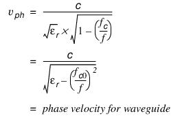
One type of dispersive media is regular waveguide. The phase velocity here is defined by:
Equation 1‑2.
Where:
• Er is the dielectric constant
• fc is the cutoff frequency of the waveguide (with dielectric) and
• fc0 is the cutoff frequency of the waveguide in a vacuum (which is what is entered).
The system will compute the required values. This information is needed for computing distances when in time domain and when adjusting reference planes.
Microstrip lines are another example of dispersive media that can be selected. Here the dimensions of the line together with the dielectric material determine the phase velocity behavior. An intermediate quantity, called the effective dielectric constant (Ɛr,eff), is used and a suggested value computed by the VNA but this value can be overridden. At low frequencies, the structure can be considered non-dispersive (like coax) with a phase velocity given by:
Equation 1‑3.
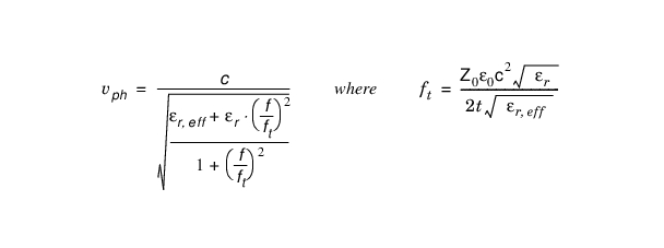
At higher frequencies when additional mode behavior becomes important, dispersion must be handled. The dielectric constants (media-based and effective) together with a transition frequency ft are used to compute this effect which is heavily dependent on the dielectric thickness:
Equation 1‑4.
Where:
• Z0 is the characteristic impedance of the microstrip line