The following example presumes a MS464xB Series VNA is being used with waveguide adapters (since SSLT is commonly used with waveguide). WR-10 is the waveguide size used in the example, which presumes the use of mmWave extensions, but other waveguide kits can be used. In this example, a full 2-Port SSLT calibration is performed although a number of other options are available. The implications of these options are discussed in the calibration overview section.
Set the desired frequency range (Frequency menu), power (Power menu) and IFBW/Averaging (Averaging menu). The default power level varies depending on the instrument model and options, but will often be adequate for all passive and many active device measurements. The default IFBW is 1 kHz with averaging off, which is adequate for many applications.
1. Navigate to the TWO PORT CAL menu.
• MAIN | Calibration | CALIBRATION | Calibrate | CALIBRATE | Manual Cal | MANUAL CAL | 2-Port Cal | TWO PORT CAL
Note
If a previous calibration exists, the Thru Update button will be active. See Through (Thru) Update for more information.
2. Select Modify Cal Setup, then on the CAL SETUP menu, select a Cal Method of SSLT and a Line Type of Waveguide.
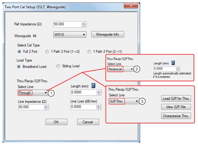
TWO PORT CAL SETUP (SSLT, WAVEGUIDE) Dialog Box
1. Through Line selected allows user entries for length, line impedance, line loss and frequency. 2. Reciprocal selected allows user entry for length. 3. S2P Thru selected provides buttons for loading, viewing, and characterization (to generate S2P files).
3. Select Edit Cal Params which will displays the TWO PORT CAL SETUP (SSLT, WAVEGUIDE) dialog box describing the calibration components (shown above).
a. Reference impedance defaults to 50 ohms. Although this does not represent the waveguide impedance, it is commonly used for conventional Smith chart referencing. Reference impedance can be changed here for certain waveguide applications or it can be changed later on a per trace basis from the DISPLAY menu.
b. Select Broadband Load. A sliding load can be used for better performance if one is available in the calibration kit. If low frequencies are included in the frequency range (< 2 GHz), then a broadband load will be used in addition to the sliding load.
c. A zero-length (or mating) thru will be used, so enter Through for the line, 0 mm for the length and 0 dB/mm loss. Zero can be entered for the reference frequency when no loss scaling is employed and the entered loss value is used for all frequencies. If a reciprocal network was being used instead of a through, the line selection would be Reciprocal and the length entered would serve as an estimate for root choice purposes.
If s2p thru was selected, the .s2p file describing the thru s-parameters would be loaded and used during the calibration. A 'characterize thru' option is also available using two previous reflection-only calibrations (with and without the thru element present) to calculate the .s2p file.
d. For a waveguide kit, select WR10 (for this example). A user-defined kit can be selected from the pull-down menu, but the cutoff frequency, the dielectric, the short offset lengths, and the load impedance (relative to the reference impedance) will have to be specified.
e. Select OK to close the dialog, then select BACK at the bottom of the menu to return to the previous level and the TWO PORT CAL menu.
4. The Port 1 Reflective Devices and the Port 2 Reflective Devices buttons display the REFL. DEVICES PORT 1 and PORT 2 menus. The six reflection standards to be measured (Short 1, Short 2, Load on each menu) will be displayed here along with the read-only fields showing the port connector choices. Connect each standard in turn, and THEN, click the corresponding button. When all six are done (and six check marks appear), click Done to return to the previous level and the TWO PORT CAL menu.
5. After measuring all six reflection standards, connect the test cable to Port 1 to complete the zero length through. Click on the Thru/Recip button to display the THRU/RECIP menu where a check mark should appear after the sweep pair. Note that the displayed graphs change during this step as the instrument must measure all four S-parameters of the through line.
6. An optional isolation step is available but is not recommended. If desired, terminate Port 1 and the end of the cable attached to Port 2 before clicking on the Isolation (Optional) button and displaying the ISOLATIONS menu.
7. When all steps are successfully completed, the Done button is available where select returns to the CALIBRATION menu where the Cal Status button is set to ON.
8. The calibration is now completed and turned on.
Note
Much like SOLT/SOLR, there is another version of SSLT using a reciprocal in place of a thru called SSLR. Reciprocal measurements (using SOLR vs. SOLT as an example) are covered in more detail in Reciprocal Measurements.