 | |
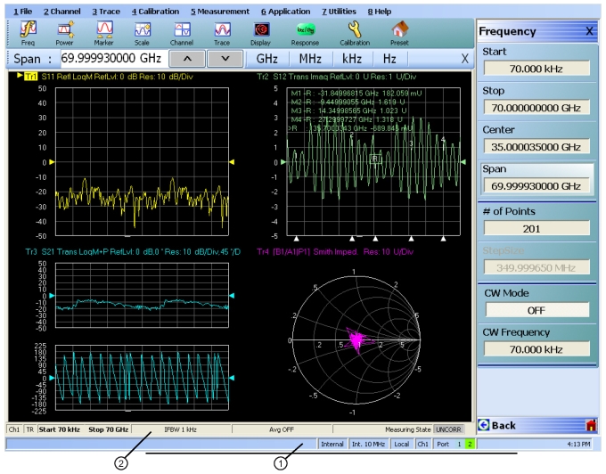
1. Instrument Status Area. | 2. Channel Status Area. If a multichannel display has been set, each channel has a separate status bar. Maximizing the channel display provides readability. |
 | |
1. Instrument Status Area. | 2. Channel Status Area. If a multichannel display has been set, each channel has a separate status bar. Maximizing the channel display provides readability. |
Status Display | Description |
|---|---|
Warning Messages | If warning messages occur, they appear on the left side of the Instrument Status Area. For example: Target Value not found for Mkr3. |
Internal Manual External GPIB | Defines the status of the system triggering. |
Ext. 10 MHz | Indicates that an external 10 MHz reference is in use. |
Int. 10 MHz | Indicates that an internal 10 MHz reference is in use. |
Local Remote | Local means the instrument is being controlled from its front panel and menu system. Remote means a remote control such as a GPIB controller is in use. |
Ch# | Displays the channel number of the active channel. For example, Ch2 means that Channel 2 is selected and active. |
Port 1/Port 2/Port 3/Port 4 | Highlights the port that is being driven. 2-Port VNAs cycle between Port 1 and 2. 4-Port VNAs cycle between 1 and 4. |
Time | Displays the system time. |