 |
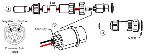
1. Thread power conductors through the gland’s components and secure the seal. 2. Connect the conductors to the connector and tighten the Allen screw to secure. 3. Install the connector to the instrument with the O-ring as shown. |
 |
1. Thread power conductors through the gland’s components and secure the seal. 2. Connect the conductors to the connector and tighten the Allen screw to secure. 3. Install the connector to the instrument with the O-ring as shown. |
 |
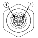
1. Positive DC lead (11 V to 24 V) 2. Negative DC lead (ground) 3. Note: the third pin has no internal connection. |
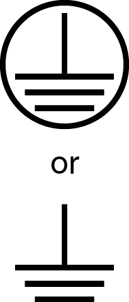
Caution  | The MS27102A chassis provides two earth ground connections. Be sure to ground the instrument chassis and any antenna installations in accordance with your local regulatory requirements. Failure to properly ground the equipment may present an electric shock hazard and contribute to static noise interference. |