Browse to load a Vision Database File (BaseStationMonitor.mdb).
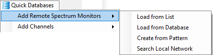
Create from Pattern
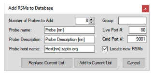
Displays a window to Add target receivers to Database. See below
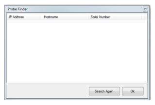
Search Local Network
Provides the window shown below. Enter the IP Address, Host name, and Serial Number and click OK or search again.
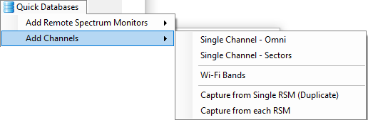
Add Channels submenu
Set the Channel Definitions.
Single Channel – Omni
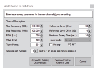
Displays the Add Channel to each target receiver dialog as shown below. Enter the trace sweep parameters for the new channels you are adding.
Note
The maximum frequency setting Vision provides is the maximum allowed on the measuring instrument up to 54 GHz. Vision does not verify the maximum input frequency range of the measuring instrument.
Start Frequency
Type or enter the channel Start Frequency in MHz. Range is 9 kHz to maximum range of measuring instrument up to 54 GHz.
Stop Frequency
Type or enter the channel Stop Frequency in MHz. Range is 9 kHz to maximum range of measuring instrument up to 54 GHz.
RBW (kHz)
Type of enter the resolution bandwidth in kHz. Range is 1 kHz to 3000 kHz.
VBW (kHz)
Type or enter the video bandwidth in kHz. Range is 1 kHz to 3000 kHz.
Trace Points
Type or enter the number of trace points. Range is 10 points to 4001 points.
Antenna port number
Type or enter the amount of port number of this entry. Range is 1 to 24. (Set to 1 on single port remote probes.)
Reference Level (dBm)
Type or enter the reference level for sweep data. Range is 60 to –100 dBm.
Reference Level Offset (dB)
Type or enter the reference level offset. Range is 0 dB to 80 dB.
Maximum Sweep Time (sec)
Type or enter the time out value for Vision Remote Spectrum Monitor. The maximum sweep time range is 3 seconds to 120 seconds.
Trace Mode
Click Trace Mode operation and then click: Normal, Rolling Min Hold, Rolling Max Hold, Average, Min Hold, and Max Hold.
Preamp
Click the Preamp check box to use a preamp for each sweep.
FFT
Click the FFT check box to use FFT (Fast Fourier Transfer) for each sweep (recommended).
Append to Existing Channel Lists
Adds the channel created from this dialog to the existing channel list.
Replace Existing Channel Lists
Removes all current entries in the channel list and replaces with new channel created from this dialog.
Cancel
Click to cancel any entries or changes.
Single Channel – Sectors
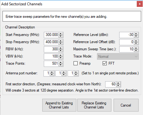
Displays the Add Channel to each receiver dialog as shown below. Enter the trace sweep parameters for the new channels you are adding.
Note
The maximum frequency setting Vision provides is the maximum allowed on the measuring instrument up to 54 GHz. Vision does not verify the maximum input frequency range of the measuring instrument.
Start Frequency
Type or enter the channel Start Frequency in MHz. Range is 9 kHz to maximum range of measuring instrument up to 54 GHz
Stop Frequency
Type or enter the channel Stop Frequency in MHz. Range is 9 kHz to maximum range of measuring instrument up to 54 GHz.
RBW (kHz)
Type of enter the resolution bandwidth in kHz. Range is 1 kHz to 3000 kHz.
VBW (kHz)
Type or enter the video bandwidth in kHz. Range is 1 kHz to 3000 kHz.
Trace Points
Type or enter the number of trace points. Range is 10 points to 4001 points.
Antenna port number
Type or enter the port number of this entry. Range is 1 to 24. (Set to 1 on single port remote probes.)
Reference Level (dBm)
Type or enter the reference level for sweep data. Range is 60 to –100 dBm.
Reference Level Offset (dB)
Type or enter the reference level offset. Range is 0 dB to 80 dB.
Maximum Sweep Time (sec)
Type or enter the time out value for Vision Remote Spectrum Monitor. The maximum sweep time range is 3 seconds to 120 seconds.
Trace Mode
Click Trace Mode operation and then click: Normal, Rolling Min Hold, Rolling Max Hold, Average, Min Hold, and Max Hold.
Preamp
Click the Preamp check box to use a preamp for each sweep.
FFT
Click the FFT check box to use FFT (Fast Fourier Transfer) for each sweep (recommended).
Antenna port number
Type or enter the port number of this entry. Range is 1 to 24. (Set to 1 on single port remote probes.) The parameters set in the above section are the same for the three ports selected here. The first probes angle (the first Antenna port number) is the first sector being adjusted and the other two will follow in 120 degree increments.
First Sector direction (Degrees measures clock-wise from the North)
Range is 0 degrees to 359 degrees. This setting applies to the first antenna port on left from the above antenna port number selections. The middle antenna port and the antenna port on the right will follow in succession in 120 degree separation.
Append to Existing Channel Lists
Adds the channel created from this dialog to the existing channel list.
Replace Existing Channel Lists
Removes all current entries in the channel list and replaces with new channel created from this dialog.
Cancel
Click to cancel any entries or changes
WiFi Bands
• Add WiFi Bands to the Channels Definitions section.
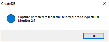
Capture from single target receiver
Click a port from the list displays the dialog shown below. Click OK to confirm or click the close button.
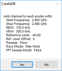
Clicking OK will display the receiver parameters below.
Capture from each target receiver
Click a port from the list displays the same dialog shown above. Click OK to confirm or click the close button. Clicking OK will display the Channel, receiver, sweep parameters, and sweep response from each receiver port in the test response data window as shown below.
Probe Installation Details List
Displays information regarding the Remote Spectrum Monitors in the field. Information includes a name, description, latitude and longitude positions, a host name or IP address, group and contact name, and the height position of the Remote Spectrum Monitor.
Channel Definitions
The Channel Definitions are the setup parameters for the remote spectrum monitors.
Mask Definitions
Mask Definitions contain the list of user created mask files that are used in determining the pass/fail limits of the measurements taken. The Mask Type and number of segments are displayed as part of the mask description in this list.
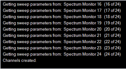
Process Log Window
The Process Log window provides data responses from the receiver, such as after the target receiver is pinged, when Locate is clicked, and receiver activity following a Create Database setup has been initiated. Any error conditions encountered during database creation will be reported in this window.