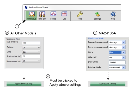
Continuous mode is available with all power sensors. This mode is user selectable from the toolbar and is the default mode of operation at startup. In this mode, the sensor is “continuously triggered”, continuously collects data. and displays average power of the input signal.
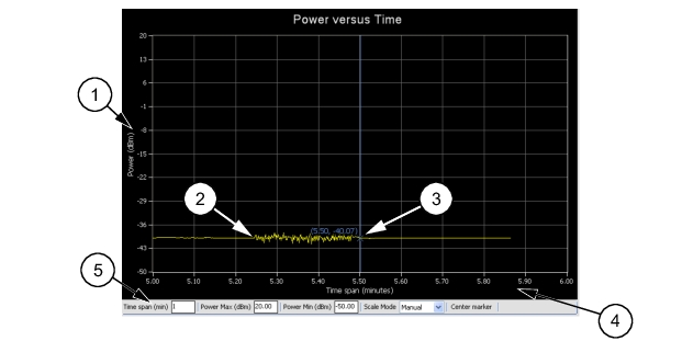
The vertical scale displays the power level in dBm, regardless of the Units settings of dBm, μW, mW, or W from the Continuous settings area.
2
Graphical trace display showing the power level as a function of time.
3
Marker showing as a vertical blue line with an x on the marker point and numerical values for the time (in minutes) and power level (in dBm). The marker is available for reading power at an instant of time. It can be dragged with the mouse and can be centered in the display via the Center Marker button.
4
The horizontal scale displays the time in minutes and may be increased or decreased from the graticule settings area. This scale increases up to a maximum of 1440 minutes.
5
Graticule settings area:
Time Span (min): Sets the current time span setting from 0.1 minutes up to a maximum of 1440 minutes. Power Max (dBm): Sets the upper power level for the vertical scale. Power Min (dBm): Sets the lower power level for the vertical scale.
• Power Max (dBm)andPower Min (dBm)settings are not available when set to Automatic.
Scale Mode: Sets the vertical scaling to Automatic or Manual.
Changes to these settings are applied by pressing the Enter key.
Duty cycle is available only with the MA24x08A, MA24x18A, MA24126A, and MA243x0A power sensors. Duty cycle correction is applied (as a percentage) to the measured average power of a pulse modulated signal to obtain the pulse power. The duty cycle correction is used to find the power during the pulse, given a measurement of the average power of a pulse modulated signal for which the duty cycle is known, and is calculated as follows:
Linear units: Pulse power = Average power / (duty cycle % / 100)
dBm: Pulse power = Average power – 10 x Log (duty cycle % / 100)
Note
On the MA24105A sensor, Duty Cycle is only used for dedicated burst average measurement.
Relative
When relative mode is turned on, relative measurement displays power changes with respect to the displayed power. To reset the power reference, turn relative mode Off, and then back on. This mode is particularly useful to study drift or measure (loss of) attenuator and (gain of) amplifiers.
Note
Relative measurement is a feature of PowerXpert and does not apply to Crest Factor, CCDF, Reflection Coefficient, Return Loss, and VSWR.
Units
Displays units of power in linear or log scale (dBm, μW, mW, or W).
Forward Measurement
Forward measurements listed below are available only with the MA24105A power sensor. Selectable forward measurement settings include:
• Average Power
• Crest Factor
• Burst Average User
• Peak Power
• Burst Average Auto
• CCDF
Reverse Measurement
Reverse measurements are available only with the MA24105A power sensor. Selectable reverse measurement settings include:
• Average Power
• Reflection Coefficient
• Return Loss
• VSWR
Video Bandwidth
Video Bandwidth settings are available only with the MA24105A power sensor. Selectable peak measurement video bandwidths include:
• Full
• 200 kHz
• 4 kHz
Aperture Time
The aperture time is the total time the sensor observes the input signal in order to make one power measurement. Settings vary depending on which power sensor is connected as follows:
MA24105A
Aperture time is not available
MA24106A
Two aperture time modes are available.
• HAT (High Aperture Time): When High Aperture Time mode is selected, the MA24106A power sensor provides more accurate measurements of TDMA signals. In this mode, the ADC acquisition time is increased and the display update rate is decreased. This mode can be useful when measuring low power, modulated signals and when changing between ranges. With HAT selected, signals with pulse repetition periods as long as 50 ms can usually be measured.
• LAT (Low Aperture Time): When Low Aperture Time mode is selected, the ADC acquisition time is decreased and the display update rate is increased. With LAT selected, the maximum recommended pulse repetition time is about 10 ms.
MA24x08A, MA24x18A, and MA24126A
If external averaging is selected, two or more of these measurements are averaged together to form the displayed power. PowerXpert automatically uses a default aperture time based upon the connected sensor. For example, when using MA24118A with a 20 ms aperture time, the sensor collects 2860 samples (with ~142 kHz sampling rate), and averages them together to compute the measurement value. Depending upon the measurement speed requirements or signal type, aperture time can be increased or decreased. For slow moving modulated signals, higher aperture time setting may be required to obtain stable readings. Refer to the “Measurement Factors” section of your power sensor chapter for more details.
Measurement Hold
Set to On: Holds the last sensor readings.
Set to Off: The sensor continues to sample measurements. Measurement hold is not used on the MA24105A.
Apply Above Settings Button
The Apply Above Settings button applies all changes made to the Continuous mode settings. Changes to these settings do not take effect until this button is clicked.