PowerXpert™ Help : Verifying MA24105A Performance : Directivity Test
 
Directivity Test
Directivity tests an MA24105A for how selective the sensor is when measuring power in a given direction of travel and rejecting signals traveling in the opposite direction.
Test Procedure
The simplified equations below give the first order approximation of this parameter:
Directivity (dB) = Power Forward (dB) – Power Reverse (dB)
Directivity Coefficient = 10(–Directivity (dB) / 20)
Directivity (dB) = –20 × log(Directivity Coefficient)
Directivity (dB) = 10 × log(Power Forward / Power Reverse), where power is in watts.
In this test, the MA24105A is tested first with power in the forward direction and then with power in the reverse direction. See Figure: Directivity Test Set Up for Power Forward and Power Reverse.
Note 
Both forward and reverse readings are taken from the Forward Average Power window on the PowerXpert display as shown in Figure: Forward and Reverse Power Reading Location.
The ratio of the two power readings are the directivity of the device assuming that both the termination and source are perfect 50 ohm matches. Since the termination and source are not perfect matches, residual effects from multiple reflections need to be accounted for by performing the following procedure.
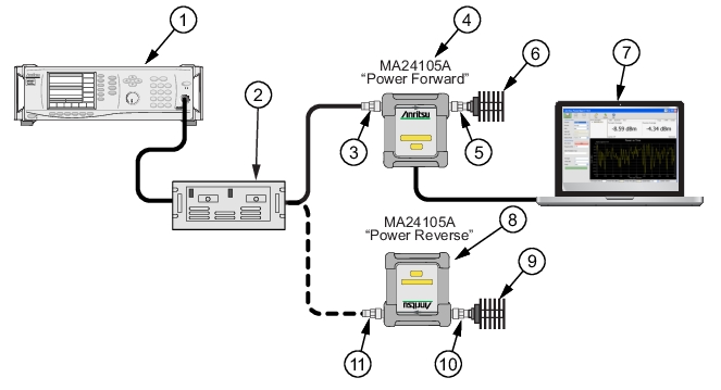
1. Turn off the RF of the synthesizer. Connect the power amplifier to the synthesizer. Connect the output of the amplifier to the input of the MA24105A. Terminate the output of the MA24105A with the specified termination. See Figure: Directivity Test Set Up for Power Forward and Power Reverse.
2. With the RF off, zero the MA24105A.
3. Set the synthesizer to the first frequency in Table: Directivity Test Measured Results and to a very low power setting and slowly increase the power until the MA24105A displays +30 dBm. Allow the devices to warm up for 30 minutes.
4. Turn off the RF of the synthesizer and zero the MA24105A again.
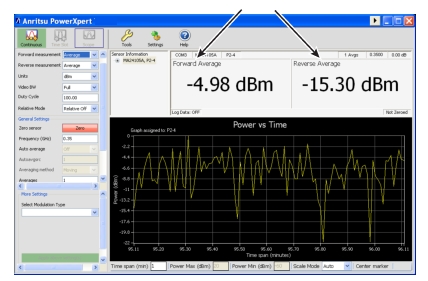
5. Turn on the RF and adjust the synthesizer until the MA24105A displays approximately +44 dBm. Confirm that the reading is stable and record this value as Power Forward in Table: Directivity Test Measured Results.
6. Turn off the RF on the synthesizer.
7. Reverse the MA24105A connections to the termination and the amplifier. Confirm that the MA24105A output is now connected to the amplifier and that the input is connected to the termination. See Figure: Directivity Test Set Up for Power Forward and Power Reverse.
8. Turn on the RF. Change the MA24105A averages if necessary to see a steady reading. Record the value as Power Reverse in Table: Directivity Test Measured Results.
9. Calculate the Actual Directivity in dB by subtracting Power Reverse from Power Forward. If the power is in watts, use the formula noted above to calculate the Actual Directivity in dB.
10. If the actual directivity is larger than the minimum allowable directivity in Table: Directivity Test Measured Results, contact Anritsu customer service.
11. Repeat the steps above for the next frequency in Table: Directivity Test Measured Results.
Directivity Test Set Up for Power Forward and Power Reverse
Index
Description
1
Synthesizer
2
Amplifier
3
RF In: N Type Connector (Torque connector at 12 lbf·in [1.35 N·m])
4
MA24105A “Power Forward” Measurement
5
RF Out: N Type Connector (Torque connector at 12 lbf·in [1.35 N·m])
6
50 ohm Termination
7
PC with Anritsu PowerXpert Application
8
MA24105A “Power Reverse” Measurement
9
50 ohm Termination
10
RF In
11
RF Out
Forward and Reverse Power Reading Location  
 
Directivity Test Measured Results


Frequency
(GHz)

Reflective
Coefficient of
Termination
Maximum
Directivity
Coefficient
A
Power
Forward
(dB)
B
Power
Reverse
(dB)
A – B
Actual Directivity
(dB)
Minimum
Allowable
Directivity
(dB)
0.35
0.071
0.040


19.1
1.0
0.071
0.032


19.7
1.5
0.071
0.032


19.7
2.0
0.071
0.032


19.7
2.5
0.071
0.032


19.7
3.0
0.071
0.032


19.7
3.5
0.071
0.040


19.1
4.0
0.071
0.040


19.1