In this test the frequency response of the sensor is tested at one low power level against a reference sensor of known measurement uncertainty. The reference sensor should be calibrated by a reputable standards laboratory using instruments with low published measurement uncertainty values. To perform the comparison, both sensors are used to measure the output power of a synthesizer with a high quality attenuator, such as the 41KC-10, on the output. The attenuator improves the source match of the synthesizer by lowering the mismatch ripples, thereby lowering the uncertainty in the comparison.
a. Connect the reference power sensor to the reference power meter using the appropriate cables.
b. Connect the USB cable between the personal computer with the PowerXpert application installed and the MA24105A power sensor under test.
c. Launch the PowerXpert application.
d. Turn the power on to all of the instruments and allow them to warm up for the amount of time specified in their respective manuals.
e. Reset or Preset all of the instruments.
f. Configure the reference meter and sensor to measure a CW signal.
g. Perform a sensor Zero and a 1 mW reference calibration on the reference sensor and meter per the manufacturer’s instructions.
h. Perform a low-level Zero of the MA24105A by disconnecting the MA24105A from the synthesizer, clicking the Zero button on the PowerXpert application, and waiting for the Zeroing message to close.
i. Connect the synthesizer to the amplifier input. Connect the attenuator to the amplifier output, then connect the appropriate adapter to the output of the attenuator.
j. Set the synthesizer to 350 MHz and a very low power output
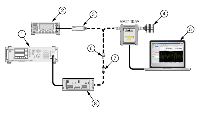
6. Disconnect the reference sensor from the synthesizer output and connect the MA24105A power sensor with the appropriate adapter and attenuator in-line. See Figure: Frequency Response Test Set Up.
7. Apply the Cal factor to the MA24105A by entering the frequency (in GHz) in the PowerXpert application, and then click Apply above settings.
12. For each frequency, compare the power difference to the maximum allowed difference specified in Table: Test Measurement Results. If the difference is higher than the maximum allowed difference, contact Anritsu customer service.
Test Measurement Results
Frequency (GHz)
A
Reference Power Measurement (dBm)
B
MA24105A Measurement (dBm)
|A-B| Absolute Value of Difference in Power Measurements (dB)