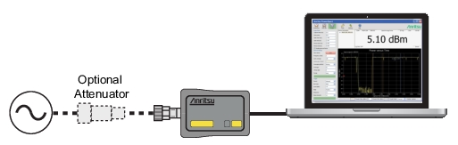
Do not apply power greater than the power sensor specifications or permanent damage may result. Connect a fixed attenuator to the output connector when power exceeds +20 dBm.
5. Read the power measurement from the Anritsu PowerXpert application window (power readings are continuous with the default setting).
Connecting the DUT
When connecting to the Type N connector of the MA24106A to a Type N female connector, observe the following proper practice for tightening the connection:
1. While holding the body of the sensor in one hand, turn the Type N Male connector nut to finger tighten the connection. Do not turn the body of the MA24106A as this will cause excessive wear to the connector.
2. Back off the connection by turning the connector nut counter clockwise ¼ turn.
3. Tighten the connection (clockwise) using a 12 in-lb torque wrench (Anritsu part number: 01-200).
Note
The Sensor has a USB 2.0 interface with a USB Type Mini-B port. The MA24106A can be remotely programmed over this USB interface. In addition to programming, the MA24106A is powered by the USB. The interface is USB 2.0 compatible, but with an interface speed of 12 Mbps.
Zeroing the Sensor
Zero the sensor before making power measurements, particularly when operating within the lower 20 dB dynamic range of the power sensor. If frequent low-level measurements are being made, check the sensor zeroing often and repeat as necessary. Before zeroing the sensor, connect the sensor to the DUT (device under test) test port and remove RF power from the connection to a level 20 dB below the noise floor of the power sensor. For the MA24106A power sensor, this level is less than –60 dBm. Leave the sensor connected to the DUT test port so that ground noise and thermal EMF (electro-magnetic fields) are zeroed out of the measurement. The sensor may also be connected to a grounded connector on the DUT or disconnected from any signal source.
To zero the sensor, click the Zero button on the application. If the sensor fails the zeroing operation, the message box states “Sensor zero failed” and “ZERO_ERROR” will be displayed on the application screen until the problem is corrected. If RF is detected, a reminder message will pop up asking to remove the RF source.
Calibrating the Sensor
The signal channel/analog signal acquisition hardware is integrated along with the RF front end of the power sensor. All of the necessary frequency and temperature corrections take place within the sensor. Therefore, there is no need for a reference calibration (at 50 MHz and 1 mW) with the MA24106A.
Applying a Calibration Factor Correction
The MA24106A power sensor has an internal EEPROM containing correction and calibration factors that were programmed into the sensor at the factory. The power sensor has an internal temperature sensor that reports its readings periodically to the microprocessor. The sensor makes all of the required calculations on the measurement once the measurement frequency has been entered by the user.