A typical noise figure measurement using Option 41 requires a few simple steps as shown below. A differential noise figure measurement with Option 48 requires an additional calibration of a second receiver, but the concepts are similar.
1. Measurement of DUT gain or S-parameters (over an appropriate frequency range and at an appropriate power level).
2. Performing an optional user power calibration over the frequencies of interest to optimize receiver calibration accuracy.
This step is performed using the internal power cal routine in the Power Menu and verifies absolute power at the test port (usually at the end of the test port cable).
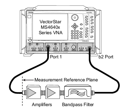
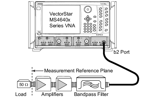
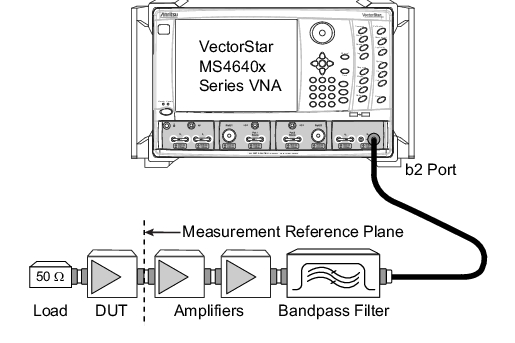
3. Assembly of composite receiver for the noise figure measurement.
This step usually includes the Uncertainty Calculator to determine the optimum preamp gain required for acceptable measurement uncertainty.
Note that the composite receiver is connected directly to the sampler via the b2 port. This is done to improve the noise figure performance of the receiver.