The receiver cal offset is a file that can be used to modify the receiver calibration used in noise figure measurements when it is known that there are some power discrepancies within that receiver cal. Examples of this situation include:
• The only power calibration that could be performed was at a higher level than that where the receiver calibration was performed and one wishes to correct for the frequency response of a pad/attenuator (or other means of power reduction) used for the receiver cal.
• The source used for the receiver calibration had some harmonic content that could cause inaccurate power readings relative to the receiver calibration readings. Knowledge of these harmonic levels can be used for a correction.
• There are other known inaccuracies with the power calibration (due to fixturing, bandwidth, etc) that one wishes to correct for.
A common scenario for using this function is in mmWave noise figure measurements when high dynamic range power sensors are not available (bullet 1 above) and a factory receiver calibration of the mmWave module is available to help. This case will be covered in detail at the end of the section.
Loading Receiver Cal Offset
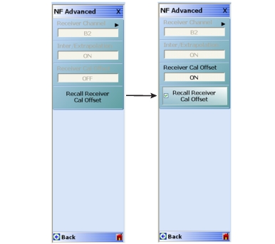
The receiver cal offset process simply involves loading a file. The menu button to load the file is shown in Figure: NF Advanced Menu - Receiver Cal Offset Functionality. Once a file is loaded, a check box appears and the correction then can be turned off and on (also suggested in the same figure).
NF Advanced Menu - Receiver Cal Offset Functionality
(Menus shown here are for Option 41. The appearance differs with Option 48, but the same functionality is available for each receiver path.)
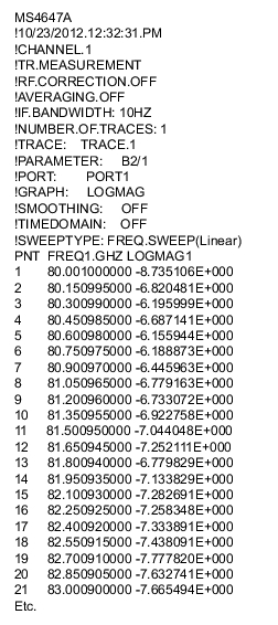
The file format is a standard VectorStar .txt file and should be the result of a Save Data operation with a single trace enabled in Log Mag display format. An example segment of such a file is shown in Figure: Example .txt File Segment. (Note that this segment happens to be from a ME7838A mmWave system, but that is obviously not required.) The response parameter is b2/1 in this case but can be anything appropriate (usually it will be b2/1 or S21) to describe the response. The data in this file should represent the power error incurred when doing the receiver calibration: a value > 0 dB means the actual power was higher than the system thought during the receiver cal and a value < 0 dB means the actual power was lower than the system thought.
The segment of an example .txt file shown in Figure: Example .txt File Segment is the file format used for the receiver cal offset correction. The response parameter can be anything but will most commonly be S21 or b2/1.
Example .txt File Segment
Consider an example where an uncompensated adapter with 1 dB of loss was used for the receiver calibration, but was not present during the power calibration. Thus, the power seen by the receiver was 1 dB lower than what the power calibration is reporting. In this case the values in the file will all be around –1 dB. This can be measured with a simple S‑parameter measurement of the adapter (using adapter removal or reciprocal techniques as necessary if the connections required cannot be mated).
Another common example is in mm‑Wave systems where power sensors are difficult to find that operate at the desired levels for the receiver calibration (which may be –50 dBm or lower). When these measurements are performed with the 3744A-Rx direct receiver module, there is a correction path available. This module is supplied with a factory receiver calibration file that one can use to back–propagate accuracy to the source power so that when one performs the “real” receiver calibration for noise figure (with a pre‑amplifier/filter assembly attached), the correct receiver calibration values can be obtained indirectly. The process can be described as follows.
Setup From Transmission/Reflection Mode
1. Connect the desired source reference plane to the 3744A-Rx module at the target power level (–60 dBm for this example). Load the provided factory receiver calibration file. Set the frequency range to the one desired for the noise figure measurement (with an adequate number of points) and set the display for single trace, b2/1 | P1, log mag.
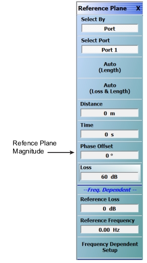
2. Set the reference plane magnitude to correct for the intended power level (–60 dB in this case) as shown in Figure: Reference Plane Settings. The resulting data then represents an error from the ideal power level and helps to describe the actual source power in a nominal bandwidth of interest.
Reference Plane Settings
3. Save the resulting data as a .txt file. This forms the receiver cal offset file for the measurement.
4. Now connect the rest of the assembly for the noise figure measurement (pre-amplifiers and filters normally) between the 3744A-Rx module and the source reference plane leaving the power setting the same. Perform the receiver calibration on this setup and save that file as normal.
5. Activate Noise Figure Mode and select BB/mmWave (3739 Test Set).
Setup From Noise Figure Mode
6. To perform the noise figure calibration, load both the receiver calibration file from step 4 and the receiver cal offset file from step 3 using the appropriate menu items. The new .txt file is loaded using the Advanced\Recall receiver Cal Offset selection.
7. Load DUT S‑parameters and perform the noise calibration as usual.
8. The display is now providing corrected noise figure measurements.
Closing Comments
The process described here can leave residual uncertainties on the order of 1 dB. The values increase as the power level required for the receiver calibration drops. This is in part due to uncompensated harmonic effects. A modified procedure is available to help reduce uncertainties due to these effects and it is detailed in application note 11410-00878 “Procedure for a Higher Accuracy Receiver Calibration for Use in mmWave Noise Figure Measurements.”