Calibration Kits, Verification Kits, and Components
Anritsu and other vendors provide calibration kits for a variety of algorithms and circumstances. In all cases, certain information must be provided to the VNA in order to complete the calibration, but the nature of that information varies by kit and application.
Calibration kits contain the precision components and tools required to calibrate the VectorStar MS464xB Series VNA for up to a complete 12-term error-corrected measurement. The calibration kits are available as automatic calibrator units or as manual calibration kits. A set of verification kits is also available to verify the accuracy of the calibration kits and the instrument settings.
Calibration/Verification Equipment Part Numbers and General Specifications
The following table summarizes the equipment related to calibration procedures.
Calibration Equipment Listing (1 of 3)
Part Number
Name
Specifications
Connectors
Precision AutoCal Modules
36585K-2M
Precision AutoCal Module, K
70 kHz to 40 GHz
K (m) to K (m)
36585K-2F
K (f) to K (f)
36585K-2MF
K (m) to K (f)
36585V-2M
Precision AutoCal Module, V
70 kHz to 70 GHz
V (m) to V (m)
36585V-2F
V (f) to V (f)
36585V-2MF
V (m) to V (f)
Standard AutoCal Module
36581KKF
Standard AutoCal Module, K
40 MHz to 20 GHz
K (m) to K (f)
Matched Adapters for 36581KKF AutoCal Modules
36583S
Matched Adapters Set, K
K (f) to K (f) (2 each) K (f) to K (m) (2 each)
36583L
Matched Adapters Set, 3.5 mm
K (f) to 3.5 mm (f) (2 each) K (f) to 3.5 mm (f) (2 each)
36583SMA
Matched Adapters Set, SMA
K (f) to SMA (m) (2 each) K (f) to SMA (f) (2 each)
SMA Connector Manual Calibration Kits
3650A
SMA/3.5 mm Calibration Kit
Without sliding loads
SMA/3.5 mm
3650A-1
SMA/3.5 mm Calibration Kit
With sliding loads
SMA/3.5 mm
K Connector Manual Calibration Kits
3652A
K (2.92 mm) Calibration Kit
With pin depth gauge
K
3652A-1
K (2.92 mm) Calibration Kit
With pin depth gauge and sliding loads
K
3652A-2
K (2.92 mm) Calibration Kit
No pin depth gauge or sliding loads
K
3652A-3
K (2.92 mm) Calibration Kit
With pin depth gauge and .s1p characterization
K
3652A-4
K (2.92 mm) Calibration Kit
With .s1p characterization
K
Type N Connector Manual Calibration Kit
3653A
Type N Calibration Kit
With fixed loads
Type N
V Connector Manual Calibration Kits
3654D
V (1.85 mm) Calibration Kit
With pin depth gauge
V
3654D-1
V (1.85 mm) Calibration Kit
With pin depth gauge and sliding loads
V
3654D-2
V (1.85 mm) Calibration Kit
No pin depth gauge or sliding loads
V
3654D-3
V (1.85 mm) Calibration Kit
With pin depth gauge and .s1p characterization
V
3654D-4
V (1.85 mm) Calibration Kit
With .s1p characterization
V
V Connector MultiLine Calibration Kits
3657
V (1.85 mm) Multi-Line Calibration Kit
Without shorts
V
3657-1
V (1.85 mm) Multi-Line Calibration Kit
With shorts
V
W1 Connector Calibration/Verification Kit
3656B, 3656C, 3656C-5
W1 (1 mm) Calibration Kit
With fixed loads
W1 (1 mm)
3656B-3, 3656C-3, 3656C-6
W1 (1 mm) Calibration Kit
With .s1p characterization
W1 (1 mm)
0.8 mm Connector Calibration/Verification Kit
3659
0.8 mm Calibration Kit
With fixed loads
0.8 mm
Verification Kits
3661-1
3.5 mm Connector Verification Kit
NIST traceable standards with two attenuators, an airline, and a stepped impedance airline Beatty Standard. Includes the 2300-579 Performance Verification Software application and related documentation.
3663-1
Type N Connector Verification Kit
3668-1
K Connector Verification Kit
Used with Short-Open-Load-Through (SOLT) with Sliding Load (Fixed Loads for Type N) using separately purchased 365x-1 Cal Kit and 36585X-2MF Series Precision AutoCal Module.
3669B-1
V Connector Verification Kit
Test Port Cables
3670K50-1
Ruggedized, Semi-Rigid, DC to 40 GHz
30.5 cm (12 in)
K (f) to K (m)
3670K50-2
61.0 cm (24 in)
K (f) to K (m)
3670V50A-1
Ruggedized, Semi-Rigid, DC to 70 GHz
30.5 cm (12 in)
V (f) to V (m)
3670V50A-2
61.0 cm (24 in)
V (f) to V (m)
3670.850-1
Ruggedized, Semi-Rigid, DC to 145 GHz
10 cm (3.94 in)
0.8 mm (f) to 0.8 mm (m)
3670.850-2
Ruggedized, Semi-Rigid, DC to 145 GHz
16 cm (6.30 in)
0.8 mm (m) to 0.8 mm (f)
3671KFS50-60
Flexible, Phase Stable, DC to 26.5 GHz
60 cm (23.5 in)
K* (f) to 3.5 mm (m)
3671KFK50-60
Flexible, Phase Stable, DC to 40 GHz
60 cm (23.5 in)
K* (f) to K (m)
3671KFK50-100
Flexible, Phase Stable, DC to 40 GHz
100 cm (39.3 in)
K* (f) to K (m)
3671KFKF50-60
Flexible, Phase Stable, DC to 40 GHz
60 cm (23.5 in)
K* (f) to K (f)
3671VFV50B-60
Flexible, Phase Stable, DC to 70 GHz
60 cm (23.5 in)
V* (f) to V (m)
3671VFV50B-100
Flexible, Phase Stable, DC to 70 GHz
100 cm (39.3 in)
V* (f) to V (m)
3671W1-50-1
Flexible, Phase Stable, DC to 110 GHz
10 cm (3.94 in)
1 mm (f) to 1 mm (m)
3671W1-50-2
Flexible, Phase Stable, DC to 110 GHz
13 cm (5.12 in)
1 mm (f) to 1 mm (m)
3671W1-50-3
Flexible, Phase Stable, DC to 110 GHz
16 cm (6.30 in)
1 mm (f) to 1 mm (m)
* Ruggedized style for VNA test ports. Does not fit standard K (m) or V (m) connectors.
Universal Test Fixtures (UTF) and Right Angle Launchers
3680-20
UTF, DC to 20 GHz
0.5 cm (min) to 10 cm (max)
3.5 mm (f) to (f)
3680K
UTF, DC to 40 GHz
0.5 cm (min) to 5 cm (max)
K (f) to K (f)
3680V
UTF, DC to 60 GHz
0.5 cm (min) to 5 cm (max)
V (f) to V (f)
36801K
Right Angle Launcher, DC to 40 GHz
1 cm (min) to 4 cm max
36801V
Right Angle Launcher, DC to 60 GHz
0 cm (min) to 2 cm (max)
AutoCal™ Automatic Calibration Modules
The auto calibration process represents both a calibration kit and an algorithm that can be used to speed up the calibration process with extremely high accuracy and a minimal number of manual steps.
The 36585X AutoCal module calibrates the VNA by a process known as “transfer calibration.” There are a number of impedance and transmission states in the module designed to be extremely stable in time and these states are carefully “characterized,” generally by the Anritsu factory but also in a customer laboratory in certain cases. When the same states are re-measured during an actual calibration, and the results compared to the characterization data, an accurate picture can be generated of the behaviors and error terms of the VNA and setup being calibrated.
A very high calibration accuracy is maintained through the use of certain principles:
• The use of many impedance and transmission states.
• The creation of very stable states that are further enhanced with a constant-temperature thermal platform inside the module.
• The use of very reliable and repeatable solid-state switching constructed to provide a great variety of state impedances (for better calibration stability) and clean transmission paths.
• The use of a very careful characterization process that can generate excellent starting data.
The resulting accuracy can exceed that obtained with a typical mechanical calibration performed in a laboratory. The AutoCal results may not be better than that of an exotic manual calibration (such as is performed during factory characterization) but will be far better than that done typically. Since it is a very high performance calibration, connector care is of the utmost importance and is discussed in detail later in this chapter.
The AutoCal consists of the calibration module itself, a separate external power supply, a control cable that runs to the VNA, and the characterization data provided on a USB memory device.
AutoCal Calibrations Available
Of the various calibration types described for the instrument, most are available with the AutoCal unit. Frequency response calibrations are omitted since the AutoCal unit would provide no benefit in these cases (since only a through or high reflect standard is needed for these calibrations). Available calibrations include:
• Full 2-Port calibration
• Reflection only (full 1-Port calibration); either port or both can be specified
• 1-Path 2-Port (1p2p); either direction can be specified (i.e., calibrate S11 and S21 or calibrate S22 and S12)
SOLT Kits (3650x and 3654x)
These kits, all based on short-open-load-through, require data describing all of the reflection standards (provided by the factory) be loaded into the instrument on a serial number basis. If this media (a USB key) is not available, average default coefficients are available within the VNA that may suffice for some measurements.
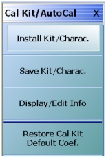
Typically these calibration kits are loaded using the CAL KIT/AUTOCAL utility menu (Figure: CAL KIT/AUTOCAL Utility Menu) but user-defined kits can also be created using the parameters described above. If calibration kits from another manufacturer are used or to create a calibration kit, the following parameters are typically entered into one of the user-defined kits:
• Open definition (M and F typically)
• Short definition (M and F typically)
• Load definition (M and F typically)
CAL KIT/AUTOCAL Utility Menu
The CAL KIT/AUTOCAL utility menu is shown here. This menu allows calibration kit details to be loaded from external files (as provided with Anritsu calibration kits), saved to a file (for user-defined cal kits), defaulted (for standard connector types), or simply displayed.
An option on the cal kit is available that provides .s1p data for all of the standards in the cal kit. A calibration using the .s1p definitions can provide enhanced accuracy over that generated using the modeled coefficients.
LRL Kits (3657/3657-1)
These airline-based kits use the LRL algorithm so much less definition of components is required. Reflects may be part of the kit but the only piece of information here is an offset length that is used to help with root selection (and is hence somewhat non-critical). The line lengths are the other parameters and they mainly serve for reference plane placement. All of these parameters must be entered manually since there are a large number of lines in the kit and usually only 2 or 3 will be used per calibration. Details on line selection and the trade-offs involved are discussed in the LRL/LRM section to follow.
Items as part of the definition:
• Line lengths (at least 2)
• Reflect offset length
Broadband SOLR/SSST kits (3656x and 3659x)
These kits, intended for use with the broadband ME7838X systems (incorporating the MS464XX), allow defined standard calibrations to 110 GHz and above. The 3656X kit is based on the 1mm connector and the 3659X kit is based on the 0.8 mm connector (for calibrations to 145 GHz). These kits combine open/short/load standards with multiple offset short standards to cover the wide frequency range with excellent performance. The Broadband calibration type is available that automatically combines the use of the standards but separate SOLT and SSST calibrations can also be merged. More information is available in Chapter 17 of this guide.
As with the SOLT kits, a USB stick is provided that contains coefficients for the kit and an option with .s1p definitions is available for the 3656X kit. If the data for the particular kit is not loaded, average coefficients will be used by default.
Offset Short Waveguide Kits (3655X)
Waveguide calibration kits based on offset short calibrations are also provided for different waveguide bands. Here two different offset-length shorts (accomplished with flush shorts and two different insert lengths), loads, and a through must be specified. Some of the standard kits are pre-defined and user-defined kits are possible as usual. Additional pieces of information here due to line type are the cutoff frequency and dielectric constant. Items as part of the definition:
• Load definition
• Short 1 definition
• Short 2 definition
• Waveguide cutoff frequency
Microstrip/Coplanar Waveguide Kits for the UTF (36804-XXX)
For certain microstrip and coplanar waveguide measurements, the Universal Test Fixture (UT) can accommodate a range of substrate sizes and thicknesses (see 3680 brochure for more information). The 36804 series of calibration kits provide opens, shorts, loads and a variety of transmission line lengths on alumina that can be used for different calibration algorithms. User-defined kits must be generated based on the information provided with the kits.
On-Wafer Calibration Kits
A variety of calibration standard substrates or impedance standard substrates are available from other vendors that contain opens, shorts, loads, and transmission lines for on-wafer calibrations. A variety of calibration algorithms may be used depending on the application. For the defined-standards calibrations, a user-defined kit will have to be generated.