Before proceeding to the calibrations and some of the alternatives available, there are certain instrument setup issues that must be discussed first since they will affect the performance of all calibrations. In almost all cases, the current VNA settings will be used during the calibration so setting up the VNA as desired beforehand will help.
Frequency Start, Stop, and Number of Points
The Start Frequency, Stop Frequency, and number of points should be decided and set in the VNA before performing a calibration. Segmented sweeps should also be set up in advance if a more custom frequency list is desired.
Harmonic Sweep Setup
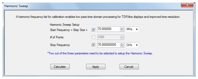
For certain applications using low pass time domain transforms (requires Option 2; see Measurement—Time Domain (Option 2) of this guide), there is a specific type of frequency list that is required called a ‘harmonic sweep’ and there is a setup tool under the Calibration menu to help with this. This frequency setup, where the start frequency is equal to the step frequency, allows higher resolution time domain impulse response plots and step response plots without using interpolation. The tool dialog is shown below and allows one to choose the dominant parameters among start frequency, stop frequency and number of points. Once entered and the calculation performed, the non-dominant parameter (and then the other parameters as necessary) will be adjusted to create the appropriate harmonic sweep. One can then proceed with the calibration as usual.
HARMONIC SWEEP Setup Dialog
Example 1:
One selects start and stop frequencies to be dominant and enters a 70 MHz start and 70 GHz stop. The system will select 1000 points and this creates a list of 70 MHz, 140 MHz,...70 GHz.
Example 2:
One selects start and stop frequencies to be dominant and enters a 27 MHz start and 20 GHz stop frequency. Since the stop frequency is not an integer multiple of the start, these constraints cannot hold. The system will assign super-dominance to the stop frequency and try to get as close as possible on start. The result would be:
• Start 27.100271 MHz
• Number of points 738
• Stop 20 GHz
There are cases when both start and stop will move slightly due to frequency resolution limits and the requirement for an integer number of points.
In other dominance cases, the frequency selections will win out over number of points. If another priority is desired, the parameters can always be entered manually on the Frequency menu.
Note
If a calibration is applied at the time the setup is run or a different sweep type is in use (e.g., segmented sweep), those will have to change before the harmonic sweep can be applied and a warning dialog will appear to allow the user to choose if that should happen.
IF Bandwidth, Averaging and Power
These parameters control the digital filtering and post-processing that determine the effective noise floor, the amount of trace noise and, in some special cases, the immunity to interfering signals. The trade-off for improved noise performance is slower sweep speed.
• IF Bandwidth (IFBW)
Settings of 1 Hz to 1 MHz are allowed with the RMS trace noise ranging from <1 mdB at the low end to a few hundred mdB at the high end (for high level signals, more for lower level signals). Sweep time will be roughly proportional with the reciprocal of IFBW once below 100 kHz IFBW.
• Point-by-Point vs. Sweep-by-Sweep Averaging
• Point-by-Point averaging incurs additional measurements at each given frequency point and will increase sweep time roughly proportionally. Because the additional measurements are taken at once, the effect is similar to proportional change in IFBW.
• Sweep-by-sweep averaging acquires additional measurements on subsequent sweeps and is better at removing lower frequency variations than point-by-point averaging or IFBW reduction. Sweep-by-sweep averaging is a rolling average so the time to fully stabilize from a sudden DUT change is roughly proportional to the average count.
• Power
Port power is somewhat less critical because of the excellent linearity of the MS464xB Series VNA receivers, but any step attenuator settings must be selected before the calibration. Because changing the step attenuator settings alters the RF match in the measurement paths as well as insertion loss, changing them will invalidate the calibration.