Preparing a Sliding Load (Termination) Calibration Kit
Sliding terminations (loads) are the traditional Z0calibration-reference devices for vector network analyzer calibration. When correctly used and perfectly aligned, they can be more accurate than precision fixed loads. However, sliding terminations have a low frequency limit dependent on connector type and must be used with a fixed load for full frequency-range coverage. The connector frequency limits are:
• 2 GHz for 3.5 mm Connector sliding loads
• 2 GHz for K Connector sliding loads
• 4 GHz for V Connector sliding loads
Sliding terminations consist of a connector, a long section of precision transmission line, and a microwave load that is movable within the transmission line. Pin depth is the relationship between the interface positions of the outer and center conductors and is the most critical parameter that you can control in a sliding termination. An example of its criticality is that an incorrect pin depth of 0.001 inch can cause a reflection return loss of 44 dB. Since you are usually calibrating to accurately measure a greater than 40 dB return loss, correct pin depth is essential.
Since setting an accurate pin depth is so important, this discussion centers on describing how to set the pin depth for male and female sliding terminations. Calibration with the sliding termination is essentially the same as described below for the broadband load.
The procedure below uses the Model 3652 Calibration Kit and its 17KF50 and 17K50 Sliding Terminations. Calibration is similar for the Model 3650 SMA/3.5mm, and Model 3654 V connector kits.
Procedure
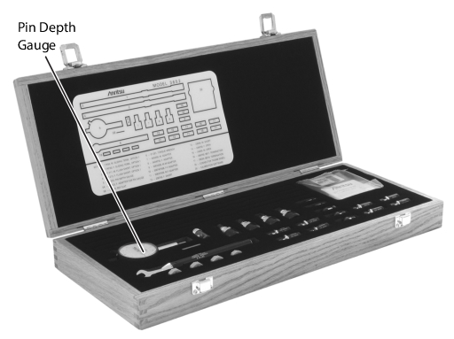
1. Remove the Pin Depth Gauge from the kit, place it on the bench top.
Note
The gauge is convertible between male and female. The following procedure describes the zeroing process for the female fitting. The procedure for the male fitting begins with Step 16 below.
Calibration Kit
2. Push the outer locking ring towards the gauge to expose the center pin.
Exposing the Center Pin
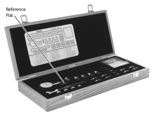
3. Take the 01-210 Reference Flat (Ref Flat) from the kit.
Reference Flat in Case
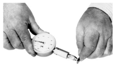
4. While holding the gauge as shown, press the Ref Flat firmly against the end of the exposed center pin.
Setting Pointer to “0”
5. While pressing the Ref Flat against the center pin, check that the pointer aligns with the “0” mark. If it does not, loosen the bezel lock screw and rotate the bezel to align the pointer with the “0” mark. Tighten the bezel lock screw.
Note
Gently rock the Ref Flat against the center pin to ensure that it is fully depressed and you have accurately set the gauge for zero.
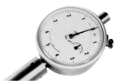
Dial Bezel and Pointer at “0”
6. Remove the Sliding Termination with the female-connector (17KF50, for this example) from the kit, and slide the load all the way toward the end closest to the connector.
F-F Sliding Terminator, Towards End Closest to Connector
Caution
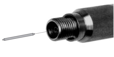
The center pin of the sliding load is floating. The load should be sighted from the connector end and rotated to allow gravity to pull the center pin such that it is concentric with the outer housing. Note the orientation of the sliding load assembly and ensure this orientation is preserved when making connections to the sliding load to avoid damaging the center pin.
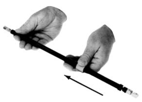
7. With either hand, pick up the sliding termination near its connector end.
Holding F-F Sliding Terminator
8. Cup the Sliding Termination in your palm, and support the barrel between your body and crooked elbow.
Holding F-F Sliding Terminator, Ready to Measure
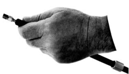
9. Remove the Flush Short by holding its body and unscrewing its connector.
F-F Sliding Terminator, Removing Flush Short
10. Ensure that the orientation of the sliding load is such that the center pin is concentric with the outer housing and install the gauge onto the end of the sliding termination.
F-F Sliding Terminator, Installing Gauge
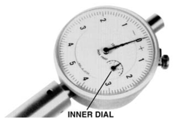
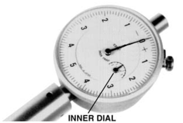
11. If the factory-set COARSE SET adjustment has not moved, the inner dial on the gauge will read “0.” If it does not, perform the Coarse Set Adjustment in Step 15 below.
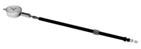
12. Place the sliding termination, with the gauge attached, on the bench top.
F-F Sliding Terminator with Attached Dial Gauge
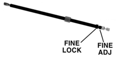
13. Loosen the FINE LOCK ring and turn the FINE ADJ ring to position the gauge pointer 0-3 small divisions on the “–” side of zero. The Sliding Load Pin Depth specification is from 0.000 inches to –0.0003 inches (0.000 in to –0.0003 in).
Using the Fine Lock Ring and Fine Lock Adjustment
14. Turn the FINE LOCK ring clockwise to both tighten the adjustment and place the pointer exactly to “0.” The Sliding Termination is now ready to use.
Note
Insure that the inner dial reads “0.” The following step is not normally necessary and it needs to be performed only if the adjustment has changed since it was set at the factory.
Fine Lock Adjustment with Gauge Inner Dial Reading “0”
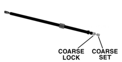
15. With the 01-211 Flush Short installed, loosen the COARSE LOCK and gently push the COARSE SET adjustment rod in as far as it will go. This coarsely sets the center conductor to be flush against the attached short. Return to Step 2 above.
M-M Sliding Terminator
16. The procedure for adjusting the male-connector sliding termination is essentially the same as that described above. The only difference is that you must install the female adapter on the end of the gauge shaft, over the center conductor. To install this adapter, proceed as follows:
a. Zero-set the gauge as described in Step 2 through Step 5 above.
b. Push the outer locking ring back toward the gauge and turn it clockwise onto the exposed threads.
c. Loosen the lock ring one turn in a counterclockwise direction.
Preparing the Gauge for the Female Adapter
17. Remove the 01-223 Female Adapter (“F ADAPTER FOR PIN GAUGE”) from the kit.
Female Adapter Location in Case
18. Install the female adapter over the center pin and screw it into the locking ring, and tighten the outer ring until it is snug against the housing.
Installing the Female Adapter on the Gauge
19. Inspect the end of the adapter, you should see no more than two exposed threads. If so, repeat Step 7 through Step 10 above.
21. Connect the gauge to the sliding termination and zero set the center pin using the FINE ADJ as previously described in Step 2 through Step 5 above.