While the T (for thru, or R for reciprocal) has been dropped from the acronym, this calibration method is a logical extension of SSST/R discussed earlier in that now more than 3 shorts may be employed. Much like mTRL (discussed in mTRL Calibration), the concept is to use an overdetermined set of standards and then select the optimal (in the sense of minimum least-squared error) set of error coefficients. In practice, this can help minimize the impact of a single (or small number of) repeatability problem(s) during the calibration or the impact of a poor definition/characterization of a single calibration standard. Also, it can avoid the need to merge a number of SSS calibrations in order to achieve a wider bandwidth as the larger starting set can automatically cover a wider frequency range.
This method is particularly attractive for higher frequency on-wafer measurements since a match is not required (although it can be used within mSSS particularly to help low frequency measurements) as match models can sometimes become complicated above 110-150 GHz. mSSS also can sometimes be preferred to mTRL on-wafer since less wafer space is required and there is less sensitivity to launch and impedance variations. This method is not a panacea however as it is a defined standards approach and, as such, does require accurate knowledge of the shorts’ reflection coefficients.
This calibration approach has been discussed extensively in the literature and, if one is creating a calibration kit for this method (e.g., for millimeter wave on-wafer measurements), some of these papers may be of assistance in selecting line lengths. This list is not meant to be exhaustive and many papers in this area exist.
• A. Lewandowski, W. Wiatr, L. J. Opalski and R. Biedrzycki, “Accuracy and bandwidth optimization of the over-determined offset-short reflectometer calibration,” IEEE Trans. Micr. Theory Techn., vol. 63, pp. 1076-1089, Mar. 2015.
• W. Wiatr and A. Lewandowski, “Multiple reflect technique for wideband one-port VNA calibration,” Proc. 16th Int. Microw., Radar, Wireless Commun. Conf., pp. 37-40, May 2006.
• J. Hoffmann, P. Leuchtmann, and R. Vahldieck, “Over-determined offset short calibration of a VNA,” IEEE MTT-S Int. Microw. Symp. Dig., pp. 47-50, June 2008.
The calibration still solves for one reflectometer at a time and there are still the three independent variables. This equation can be cast in the form:
Equation 5‑4.
Where the Ci are the defined reflection coefficients for the different shorts (usually Γie-j2βLi; the Γi are nominally -1, but more on that later), the Mi are the measured values, and the Ki are the weights (more on that later also). The row indices represent the offset short number (N total). The reflectometer terms then come from x, y, and z:
Equation 5‑5.
As can be deduced from other chapters in this guide, edj is the directivity error coefficient, epjS is the source match error coefficient and etjj is reflection tracking error coefficient for the jth port. The thru line/reciprocal choice processing (and the added-line processes for four port) are the same as for SSST/R and all of the other defined standards calibrations. The above matrix equation is solved in a least-squares sense to generate an optimal (in the LSQ sense) set of reflectometer error coefficients independently at each frequency.
The user has some flexibility in how the shorts (the Ci) are defined.
• A standard Anritsu calibration kit can be used (the 3656x 1 mm kit and the 3659 0.8 mm kit both have sets of offset short standards) and any subset of the shorts in those kits can be employed.
• A user-defined calibration kit can be employed with either modeled or .s1p definitions. Again, these kits generally contain a number of offset shorts and any subset can be employed.
• A selection of Other can be employed for a one-off definition of a short based on offset length and a loss profile (X dB/mm at a reference frequency fr and the loss defined to be flat with frequency or scale as sqrt(f/fr)).
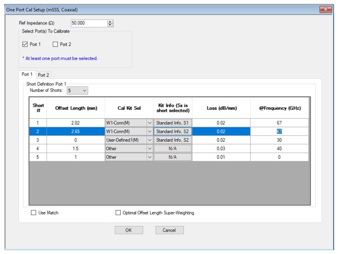
mSSS configuration for an example 1-port Coaxial Calibration Note the variety of calibration component definition formats that are possible. Up to 10 shorts can be defined.
The dialog will check that two shorts are not identical but will not directly assess the suitability of the set for the frequency range being calibrated. Warning messages will be issued if the condition number of the matrix in Eq. 5‑4 is extreme or if a near-singularity is encountered. Generally, the largest 2-3 offset length deltas will establish the lower frequency limit and the shortest 2-3 will establish the higher frequency limit as one might have guessed from the SSST sections earlier in this chapter.
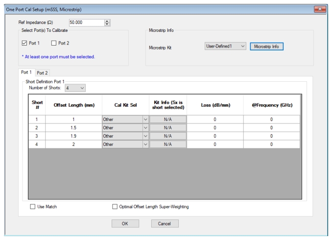
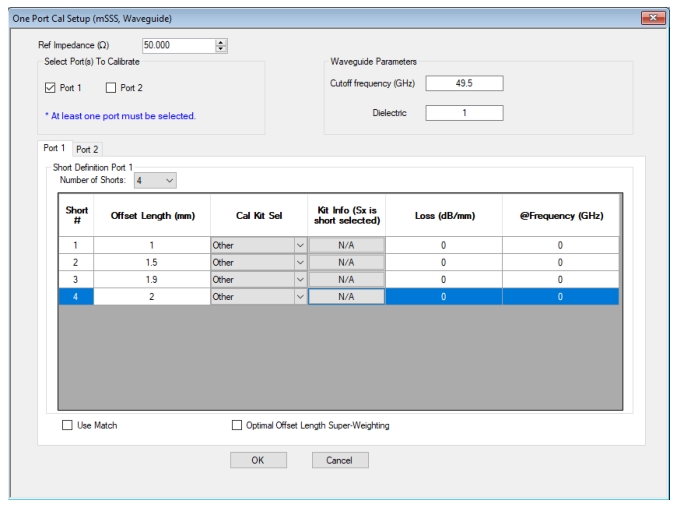
Coaxial mSSS can be useful in millimeter wave contexts as coaxial load performance may not be optimal and the related non-dispersive selection is applicable to coplanar waveguide and stripline systems for on-wafer and/or fixtured environments. Waveguide and microstrip contexts are also useful and they have very similar dialogs except the media parameters (cutoff frequency and dielectric in the case of waveguide and substrate parameters in general in the case of microstrip) must be specified globally for all of the shorts to be used. As with the other calibrations, these media parameters will propagate to the Measurement menu for use in reference plane extension and time domain processing. The waveguide and microstrip versions of the mSSS configuration dialog are shown in Figure: Microstrip mSSS Configuration Dialog Note the specification of the global media parameters. and Figure: Waveguide mSSS Configuration Dialog Note the specification of the global media parameters. (for 1-port calibrations; similar dialogs exist for 2+ port calibrations except they also have fields for thru/reciprocal information).
Microstrip mSSS Configuration Dialog Note the specification of the global media parameters.
Waveguide mSSS Configuration Dialog Note the specification of the global media parameters.
The weights Ki (in Eq. 5‑4) start off with a value of 1 so, unless the super-weighting box is checked, Eq. 5‑4 simplifies to Eq. 5‑6.
Equation 5‑6.
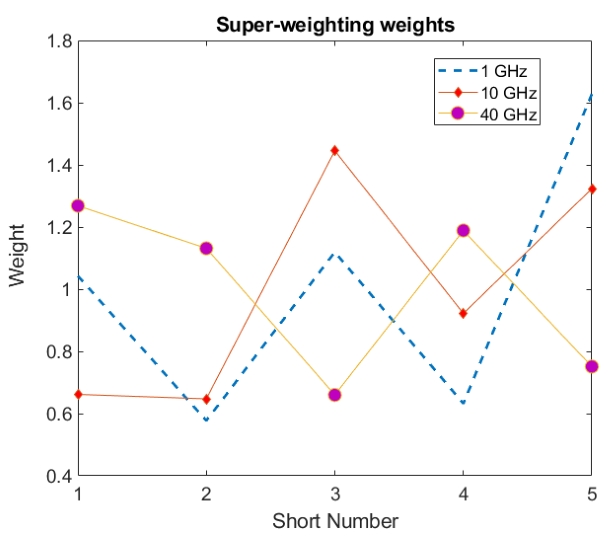
By checking the super-weighting box, weights are applied to the shorts based on a prediction of which ones are most useful to the calibration. That weight, in an approach similar to that discussed in the literature, is obtained by looking at the error coefficient sensitivity for all possible permutations of three shorts (in an SSS sense) and then mapping each individual short's contributions to those sensitivities. Geometrically, each combination of three shorts (at each frequency) can be thought to define a triangle on the complex plane and (generally) the larger the area of that triangle, the less sensitive the calibration will be. Those shorts that are part of the most large-area triangle combinations will receive the highest weight. As an example, consider a set of five lossless shorts with offset lengths of 0 mm, 1 mm, 7 mm, 3 mm, and 12 mm and this kit will be assessed at three frequencies: 1 GHz, 10 GHz, and 40 GHz. The weights chosen are shown in Figure: The super-weighting option provides additional emphasis to those shorts that contribute to larger reflection coefficient coverage and hence reduced calibration sensitivity. Weights are applied to the equations in a linear sense with a nominal value of unity..
At 40 GHz, one would expect the smaller length deltas to get higher weights and indeed that happens as shorts 1, 2, and 4 (with differences of 1, 2, and 3 mm) get the higher weights. At the low frequency extreme, one would expect the opposite. This also happens as shorts 3 and 5 (in conjunction with short 1) are favored for that frequency.
The use of super-weighting does accentuate the importance of the most bandwidth-friendly offset lengths but it does suppress, to some extent, the algorithm's ability to underweight repeatability-induced outlier measurements. Thus, super-weighting is attractive when trying to absolutely maximize calibration bandwidth (for a given set of shorts) but is not attractive in a repeatability-challenged environment (e.g., in a fixture).
The super-weighting option provides additional emphasis to those shorts that contribute to larger reflection coefficient coverage and hence reduced calibration sensitivity. Weights are applied to the equations in a linear sense with a nominal value of unity.
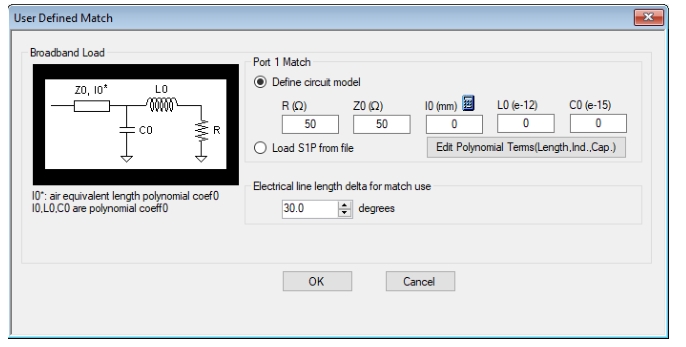
The mSSS calibration also allows the incorporation of a match standard (we realize this does not fit into the acronym) to (a) help with low end frequency coverage as offset short calibrations are always inherently somewhat bandpass in nature and (b) provide additional sensitivity suppression if some of the short standards become electrically indistinct over other parts of the bandwidth of interest. As with some other calibrations in the MS464XX system, a full load model or an .s1p file can be entered as suggested in Figure: Match Info Dialog This dialog is available to define a match standard should its use be desired within the mSSS calibration.. This dialog is only available if the Use Match box is checked.
Match Info Dialog This dialog is available to define a match standard should its use be desired within the mSSS calibration.
The decision to use the match measurement as part of the solution (it is added as another row in Eq. 5‑4 with a weight set to twice the maximum of the weights amongst the shorts) is based on the offset length differences between the shorts. A minimum delta (expressed in terms of difference in reflection coefficient phase) is computed for every permutation of three shorts among the defined shorts. If the maximum of those minimum deltas (amongst all of the permutations) is less that the entered ‘Electrical line length delta for match use’, then the match measurement will be employed at that frequency. This decision is made on a frequency-by-frequency basis.
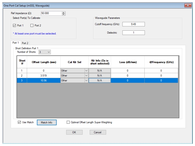
As a simplified example of this process, consider an intentionally inappropriate set of 3 offset shorts for a calibration and the resulting measurement of a DUT. The measurements will be done in Ku-band waveguide (~12-18 GHz) with offset short lengths of 0 mm, 3.519 mm and 10.56 mm using a simple 1-port calibration and the setup information shown in Figure: Setup for some example measurements to illustrate the use of the match standard. The medium is Ku-band waveguide.. The problem with this kit is the larger delta between the 0 mm and the 10.56 mm standards. At 17.08 GHz, those two shorts will have essentially the same reflection coefficient (ignoring losses) so a near-singularity is likely.
Setup for some example measurements to illustrate the use of the match standard. The medium is Ku-band waveguide.
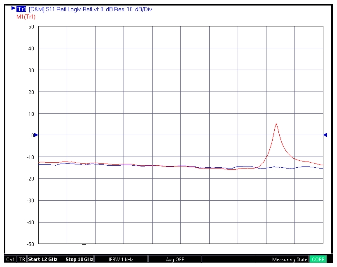
Measurements of an open waveguide flange using a defective 3-short calibration (red) and the 3-short calibration augmented by the match measurement (blue). The near-singularity in the red curve is due to the inappropriate choice of offset lengths for this frequency range.