The following example presumes an MS464xB Series VNA on a coaxial setup. On-wafer scenarios can be accommodated by modifying the entries in Step 4 below. It is assumed that a mating reference plane pair can be created (either MF in coax or zero length-thru compatible). In this example, a full 2-Port LRM calibration is performed, although a number of other options are discussed along the way. The implications of these options are further explained in the calibration overview section.
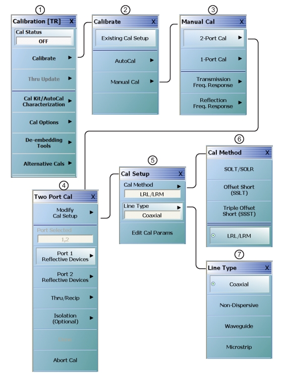
Calibration Menu Set for LRL/LRM Coaxial (1 of 2)
1. CALIBRATION menu
2. CALIBRATE menu
3. MANUAL CAL menu
4. TWO PORT CAL menu
5. CAL SETUP menu
6. CAL METHOD menu
7. LINE TYPE menu
Procedure
1. Setup the desired frequency range (FREQUENCY menu), power (POWER menu) and IFBW/averaging (AVERAGING menu). As a default, the IFBW will be 1 kHz and the averaging will be off which is adequate for many applications. The default power level will vary depending on instrument model and options but will often be adequate for all passive and many active device measurements
2. Navigate to the TWO PORT CAL menu.
• MAIN | Calibration | CALIBRATION | Calibrate | CALIBRATE | Manual Cal | MANUAL CAL | 2 -Port Cal | TWO PORT CAL
Note
If a previous cal exists, the Thru Update button will be active. See Through (Thru) Update for more information.
3. SelectModify Cal Setup and on the CAL SETUP menu, select a Cal Method of LRL/LRM and a line type of Coaxial.
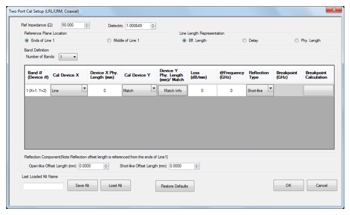
4. Select Edit Cal Params to open the TWO PORT CAL SETUP (LRL/LRM, COAXIAL) calibration components dialog box.
Calibration Setup Dialog—TWO PORT CAL SETUP (LRL/LRM, COAXIAL) Dialog Box
5. On the TWO PORT CAL SETUP (LRL/LRM, COAXIAL) dialog box, set the following:
a. The Reference Impedance establishes the impedance for the load definition, reference plane changes and Smith chart plotting. The default is 50 ohms.
b. Select Ends Of Line 1 as the Reference Plane Location. Since this example uses a zero length line, the choice makes no difference.
c. For Number of Bands, select 1. For an LRL calibration, instead of LRM as in this example, the bandwidth of the calibration will be limited by the difference in lengths between the lines. Two bands can be used (with 3 or 4 lines) to cover a larger bandwidth.
d. For this example, set Band 1 Device 1 to Line with a Line Length of 0 and Line Loss of 0 dB/mm. The reference frequency for the loss can be entered as 0. In general, this forces no loss scaling with frequency and the line loss value entered will be used at all frequencies.
e. Set Band 1 Device 2 to Match since we are performing an LRM calibration. A specific match (or load) model may be entered under Match Info, but this example uses the default of 50 ohms.
f. For the Type of Reflection select Use Short-like Component. This implies the impedance is usually less than the reference impedance but it need not be precise. This information is used to help in root selection. Enter the Short-like Offset Length in the Reflection Component section at the bottom of the dialog box.
g. Click OK to accept the entries and close the dialog box. Select Back at the bottom of the Cal Setup menu to return to the previous level TWO PORT CAL menu.
6. The menu-by-menu procedure is shown in the figure below.
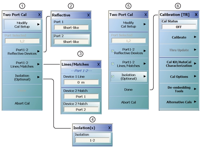
Two Port LRL/LRM Coaxial Calibration Procedure Menus (1 of 2)
1. The TWO PORT CAL menu with link/completion buttons for Port 1-2 Reflective Devices, Port 1-2 Lines/Matches, and Isolation (Optional). The Done button is not available.
2. REFLECTIVE Port 1-2 Menu
3. LINES/MATCHES Menu
4. Optional ISOLATIONS Port 1-2 Menu
5. TWO PORT CAL menu after all calibration procedures successfully completed. Note Done button is available.
6. CALIBRATION Menu with Cal Status set to ON.
7. On the TWO PORT CAL menu (above in Figure: Two Port LRL/LRM Coaxial Calibration Procedure Menus (1 of 2)—#1), select the Port 1-2 Reflective Devices button and its linked REFLECTIVE menu (Figure: Two Port LRL/LRM Coaxial Calibration Procedure Menus (1 of 2)—#2). In this example, the short-like reflective device must be measured at both ports. After the device is connected to a given port, click the corresponding button (a check mark will then appear after the measurement). Click on Back when done with this step to return to the TWO PORT CAL menu.
8. Connect the reference planes together to form the 0 (zero) length line. Select Port 1-2 Lines/Matches and on the LINES/MATCHES menu (Figure: Two Port LRL/LRM Coaxial Calibration Procedure Menus (1 of 2)—#3), click on Device 1 Line (0m). Sequentially connect the load (or loads if two models were entered for two physically separate loads) and click the corresponding buttons. For this example, repeat for Device 2 Match at Port 1 and then Device 2 Match at Port 2. As before, check marks will appear when a given step is completed. Click BACK when completed and then DONE.
9. An optional isolation step using the Isolation (Optional) button and the linked ISOLATIONS menu (above Figure: Two Port LRL/LRM Coaxial Calibration Procedure Menus (1 of 2)—#4) is available but is generally not recommended. If desired, terminate Port 1 and the end of the cable attached to Port 2 before clicking on the Isolation 1-2 button.