Since there are a number of choices involved in setting up the LRL/LRM family of calibrations, some additional hints and points of emphasis may be of assistance:
• Reflect offset lengths are referenced to the ends of Line 1. These lengths are all air-equivalent lengths. The line length entries for the transmission lines are also air-equivalent. If the lengths are known in terms of time delay, the air-equivalent length is given by:
time delay (seconds) x 2.9978 x 10⁸ (m/s)
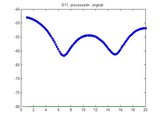
• The frequency breakpoint for multi-band calibrations is calculated from the geometric mean of the theoretical upper limit of the low band and the theoretical lower limit of the upper band. The former is calculated based on the 160 degree delta frequency and the latter is calculated from the 10 degree delta frequency. This decision is somewhat arbitrary and is heavily dependent on the materials involved and uncertainties required. With relatively lossy lines, one can approach the limits more closely than with low-loss lines. The impact is also dependent on transmission line quality. If both lines have an impedance of, for example, 50.1 ohms and one measured a theoretical –80 dB termination, the result would be predictable limited by the line impedance imperfection to about –61 dB at all frequencies. If instead, one line was 50.1 ohms and one was 50.2 ohms, then one gets progressively more effect near the theoretical edge frequencies as shown in the figure below.
Effect of Line Impedance Problems as Line Length Delta Approaches Theoretical Band Edges
The effect of line impedance problems gets magnified as the line length delta approaches the theoretical band edges (the result for a high RL termination measurement when calibrated with unequal line impedances is shown here). This should be considered when deciding on the 2-band breakpoint frequency.
• When doing two band TRL/LRL calibrations, the orientation of the lines between bands can sometimes be confusing. The larger line delta should always be in band 1 (the lower frequency section).
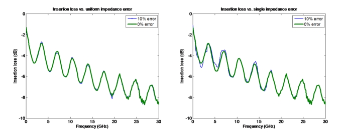
• The TRL family of calibrations is more sensitive to asymmetries in standards (for example: different reflects on the two ports, lines of different impedance) than to problems in the standards themselves. When creating a custom calibration kit, this can be an important point. As an example, the effect on the measurement of a mismatched delay line is shown in Figure: TRL/LRL Sensitivity to line impedances when there was a global 10% impedance error on the LRL calibration lines and when the error was on only one line.
• While the reflect standard asymmetry can have an effect (particularly on reference plane positioning), this effect is usually weaker than proportionately similar errors on other standards.
• In LRM, the agreement between the actual match standard and the model used will directly impact residual directivity and the measurement of high return losses. Also, since this impedance sets the actual reference impedance of the calibration, if the characteristic of the impedance deviates from that, errors occur. In general the line impedance (for LRL) or the match impedance (for LRM and ALRM) sets the calibration reference impedance. If this value is known, the calibration can be transformed to a different reference impedance using the impedance transform function under the Measurements menu. In ALRM, the accuracy of the net match model will largely determine residual directivity. If the match standard being used is topologically complex for the frequency range being used, the simplified model being optimized for the match may not be adequate and higher residuals will result. As mentioned earlier, ALRM is most successful with physically small and simple matches as might be found in an on-wafer calibration environment.
• While line impedance is central, another critical assumption is the how well the lines approximate ideal transmission lines (i.e., transmission acts like exp(-γ L) where γ is the complex propagation constant). Where the most problems occur is when there are significant launch admittances associated with the line that vary from line to line (non-repeatable connectors, non-repeatable probe placement, etc.). If the admittances were constant, they would just get built into the calibration. If they are large and variable, these can be the largest error source. Care is advised particularly in LRL line sets on a PC board that the connectors are setup as identically as possible, or if probing, that the probe placement is as consistent as possible.
• At the bottom of the dialog is a ‘save kit’ and ‘load kit’ capability. This allows one to save and recall an entire LRL/LRM/ALRM definition like a calibration kit independently of the instrument setup. There is, of course, a correlation to the rest of the instrument setup because of breakpoint frequencies in multiband configurations but this allows one to keep a number of kits describing line sets (or lines plus matches) in a central location. The media type is stored as part of the LRL/LRM calibration kit.
TRL/LRL Sensitivity to line impedances
TRL/LRL is more sensitive to differences between the line impedances than to the absolute line impedance (although problems on that will shift the reference impedance of the calibration).
• When using microstrip media, it is easy to confuse entries with respect to physical and effective lengths. Make sure the media parameters and radio-button selections are set as needed. The reflection offset entries are always in physical length for microstrip (note the message in the dialog) unlike for the other media types.
• - TRL and TRM dialog options are also available. Algorithmically, these are the same as LRL and LRM except line length 1 must be zero. Thus, the dialogs are somewhat simplified and reference plane considerations are less complex. The other topics discussed in this chapter still apply.