Although many implementations are possible, the algorithm here makes use of an optimal line at each frequency (discussed in the first reference above) which has the best line length deltas for that frequency (recall the discussion in the previous chapter that line length deltas should not be close to 0 or 180 degrees). The pairing of this line with all of the other lines forms the set of measurements used in the least-squares analysis. There is considerable freedom in how many lines are used but the shortest line length delta in the set should satisfy the highest frequency to be measured (~<160 degrees of difference at the highest frequency) and the longest line length delta should satisfy the lowest frequency to be measured (~>20 degrees of difference at the lowest frequency although much lower differences are tolerable if the lines have any noticeable loss). Adding additional lines can help further reduce repeatability effects or mitigate the effects of characteristic impedance or propagation constant variation amongst the lines.
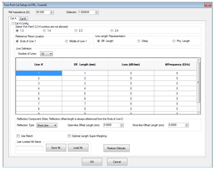
As can be seen in the setup dialog in Figure: mTRL Setup Dialog Box, the number of lines is selected and then the line lengths entered. The line lengths entered are used for the optimal line selection and the line length delta weighting so the values are important but extreme precision is not. An exception is the line 1 length if the 'ends of line 1' reference plane position is selected since, in that case, line 1 length will be used to rotate out to the selected reference plane. As with the LRL family, the reference planes inherent to the calibration are in the middle of the line space.
Note
The line loss and line frequency are only used as part of this reference plane rotation step.
mTRL Setup Dialog Box
As with the LRL family, the line length presentation can be selected (and values will be recalculated on the fly using the current media definition) as effective length, physical length or delay. The reflection type is also selected (and offset lengths entered) just as in the LRL family. The calibration kit can be saved and recalled as with the LRL family but the file name extensions are different (.mlcf vs. .lcf; both are text-based XML formats though). The calibration kit files are not interchangeable between the LRL/LRM family and mTRL.
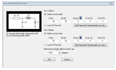
The match element is used quite differently from in LRM (where it was assigned to be used in a specific band or bands) and is slightly distinct from the least-squares solving process used for the rest of mTRL. The premise is if none of the line length deltas are entirely satisfactory for a given frequency point, the match measurement (referenced to the match model provided by the user) will be used for that frequency point. This criterion is set with a minimum electrical length delta entry (expressed in degrees) as shown in the Match Info dialog in Figure: Match Information Dialog Box. If the line length deltas fall below that value at a given frequency point, the match data will be used (in an LRM-sense with line 1 data) at that frequency. The default value is 20 degrees. Checking the 'Use Match' box enables the Match measurement and access to the Match Info dialog box (USER DEFINED MATCH DEVICES).
Match Information Dialog Box
The match information dialog (Figure: Match Information Dialog Box) allows the match model (or .s1p file) to be entered for the standard to be used at each port. The electrical line length delta entry determines when the match data will be used.
The Optimal Length Super-Weighting checkbox applies a weighting to the least-squares computation process to further emphasize the contributions of lines whose deltas relative to the optimal line are closest to 90 degrees at each frequency. While there is already a certain amount of weight applied to this case in the basic method, the selection of Super-Weighting further increases that emphasis. Outlying measurements will be less under-weighted than in the basic method so the use of this check box provides less repeatability immunity but increased line singularity immunity. It may be most useful when the line length collection is skewed so the length delta choices are unfavorable at some parts of the frequency span.