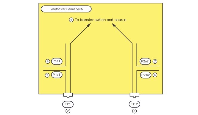
Simplified Block Diagram of the MS464xB Series VNAs
1. To transfer switch and source.
2. TP1—Test Port 1
3. P1b1—Reference Receiver Port a1
4. P1a1—Test Receiver Port b1
5. TP2—Test Port 2
6. P2b2—Reference Receiver Port a2
7. P2a2—Test Receiver Port b2
As this is a 2-Port VNA, there are four unique receivers that are performing the measurements: a reference receiver associated with each port (a1 and a2) and a test receiver associated with each port (b1 and b2). An absolute power calibration, which is the receiver calibration, can be associated with each of these receivers.
Note that although the receivers are shown here as associated with couplers, this need not always be the case. With Option 51, 61 and 62, loops are in place between the coupler arms and the receivers, allowing direct access to those receivers. This brings up the point of receiver reference planes. The receiver calibration will establish an absolute power reference, but how the calibration is setup will establish where the reference is being established.
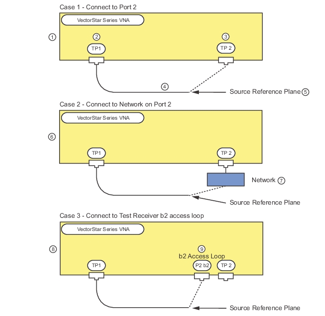
Consider the three cases shown in Figure: Three Different Receiver Reference Planes. The use of three different receiver reference planes is shown. Where the known source power reference plane is connected for the receiver calibration establishes where that power knowledge is transferred to.
Three Different Receiver Reference Planes
Case 1—Port 2 Direct
1. Case 1—Connect to Port 2
2. Test Port 1
3. Test Port 2
4. Test Cable (f-m)
5. Source Reference Plane
Case 2—Network Connected to Port 2
6. Case 2—Connect to Network Connected to Port 2
7. Network attached to Port 2
Case 3—Port 2 b2 Access Loop
8. Case 3—Connect to Port 2 b2 Access Loop
9. Port 2 b2 Access Loop—Requires VNA equipped with Option 51, 61, or 62.
In all of the cases, the source reference plane (where the power is accurately known) is at the end of the dashed cable. This will be connected in different places in the three cases thus establishing the receiver reference plane in three different places. In this case, the absolute power reference has been transferred to (all referring to the Port 2 Test, or b2 receiver calibration in this example set):
• Case 1
To Port 2
• Case 2
To the input of a network connected to Port 2 (could be a pad, a cable assembly, a switch matrix)
• Case 3
To the direct access loop input to the b2 receiver
All of these may be valid receiver reference planes depending on where one wants to connect the DUT (and, more precisely, where one wants to measure power).
The source reference plane is any plane where one accurately knows the signal level. The factory ALC calibration establishes that knowledge at the test ports with moderate accuracy (on the scale of 1 dB). It may be that greater accuracy is needed or it may be that this plane is inconvenient:
• Cable
A cable is needed to reach the receiver reference plane and it is not desired that this cable loss be neglected
• Preamplifier
A preamplifier is needed before the DUT and it is desired that this power level form the reference (if, for example, the receive-side network has very large loss and one wants a better signal-to-noise ratio for the receiver cal)
• Other
Other reasons
For these cases, a power calibration using a GPIB-controlled power meter can be performed at the desired source reference plane prior to performing the receiver calibration. Over reasonable periods of time, the power calibration accuracy can be on the order of 0.1 dB. Aspects of the power calibrations are discussed in the Sweep Types section of the Measurement Guide and in the Operations Manual.
A key point in establishing the source reference plane is that the receiver calibration needs to be informed of what that power level is. This is done through the power menu. The value entered there is used as the power reference. When using the factory ALC calibration at the port, this link is obvious. When using a power cal at some other reference plane, the power entry field on the power menu is also now linked to that reference plane. Thus in both cases, the correct power value is transferred to the receiver cal.
The relationship between the power entry fields and the Target Power field of the power calibration is important. First a few definitions:
ALC entry field:
Where the requested power is entered on the main Power menu for Port 1, Port 2, etc. (to include the >54 GHz fields for certain mmWave modes when present).
Effective power field:
The read-only fields below the ALC entry fields. These normally reflect the settings of source attenuators (if present) but play an additional role when power calibrations are active.
Target power field:
The entry area on the Power Cal submenu where the objective of the power calibration is entered.
The normal procedure is to enter the desired power at the user reference plane (where the power sensor will be connected for the power calibration). If the gain/loss between the VNA port and the user reference plane is small, the ALC entry field can be set to the same value as the Target Power. If the gain/loss is significant, the ALC field should be offset by an estimate of that gain/loss (ALC entry field should be higher if it is a loss, and lower if it is a gain). This offset need not be extremely accurate; it serves to inform the system of where roughly to set the internal sources in order to achieve the desired user reference plane power. After the power calibration is completed, the Effective power field will match the Target power. If the ALC entry field is later changed (from the value at the time of the calibration), the Effective power field will also change to reflect an estimate of the new user reference plane power. This new value is only an estimate since the calibration was not performed at that power level and the accuracy will decrease as the change from the calibrated level increases.