Target power is –20 dBm and there is about 8 dB of loss from the VNA port to the desired reference plane.
1. Set Target Power to –20 dBm and set the ALC entry field (for that port) to –12 dBm. Perform the power calibration.
2. After the calibration is successfully completed, the Effective power will read –20 dBm and the ALC entry field will remain at –12 dBm.
3. Change the ALC entry field to –15 dBm. The Effective power field will change to –23 dBm (the estimate of the new power at the reference plane).
4. Turn the power calibration off. If the ALC entry field is still at –15 dBm, the Effective power field will change to also be at –15 dBm. With the power calibration no longer applied, the system’s best estimate of the power being applied is that based on the internal power calibration.
Note that the source attenuator settings (if Option 61/62 is installed) will be reflected in the Effective power value even if no power calibration is applied.
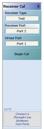
The first two menu items describe which receiver is being calibrated and the third describes the driving port and, hence, the source reference plane. Once the source and receiver reference planes are connected, the Begin Cal button can be selected. The note at the bottom of the menu indicates that a thru line should be connected between ports but what is really meant is that the source and receiver reference planes should be connected together.
During the calibration, different parameters will be displayed as the system collects the appropriate receiver data. Once complete, the calibration will be activated as shown in the Figure: RECEIVER SETUP Menu menu.