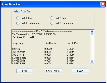
The View Receiver Table button displays the calibration values. This is sometimes valuable as a troubleshooting aid or to gain some more insight into the signal levels in a particular setup. An example Receiver Calibration Table is shown in Figure: VIEW RCVR CAL (RECEIVER CALIBRATION) Dialog Box—Typical Receiver Calibration Table. In this example, the table refers to the port 2 test calibration (b2).
VIEW RCVR CAL (RECEIVER CALIBRATION) Dialog Box—Typical Receiver Calibration Table
The receiver calibration is indexed to frequency at the receiver so two vectors of data are key (first two columns). The power level used in the calibration is also shown in the third column as a reference.
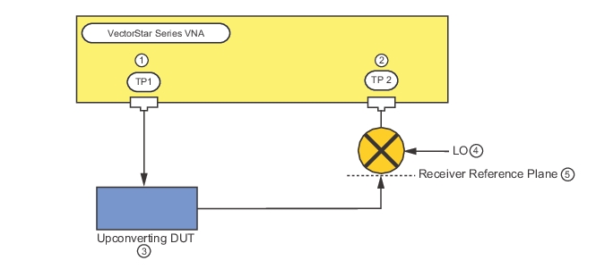
The frequency index vector brings up an important point when using receiver calibrations with multiple source mode and certain other frequency conversion modes. It is important that the frequency index match the frequencies present at the receiver reference plane so that the computations can be performed correctly. Consider the setup shown in Figure: Example of a Frequency-Translated Receiver Reference Plane that uses multiple source control (see separate section in this measurement guide and multiple source application notes for more information).
Example of a Frequency-Translated Receiver Reference Plane
1. Test Port 1
2. Test Port 2
3. Upconverting DUT
4. LO (Local Oscillator)
5. Receiver Reference Plane
The DUT in this case is up converting (for example, to millimeter wave frequencies) and a down converter is used to bring the DUT output back to within range of the MS464xB Series VNA. To measure the DUT output power, the receiver reference plane must be in the millimeter wave zone and the frequency list should be referenced here. The receiver source equation in multiple source mode can be used to help here.
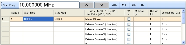
Receiver Source Equation From Multiple Source Mode
The purpose of this equation is to provide the proper frequency index for the receiver calibration. See the multiple source section for more details
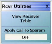
A final utility controls the interaction between the receiver calibration and ratioed S-parameters. Typically, the receiver calibration pertains to non-ratioed measurements so the correction is not applied to the non-ratioed variables prior to forming the S-parameter ratios. This is done to avoid the confusion of the receiver calibrations interacting with the regular S-parameter calibrations (SOLT, LRL/LRM). The application of the receiver cal is, by default, off for ratios. If desired, the application of the receiver cal to the S-parameter ratios can be turned on (to allow off-line ratio comparison for example) but performing a receiver calibration after an S-parameter calibration will invalidate the S-parameter calibration (as well as trace memory comparisons and other measurements).