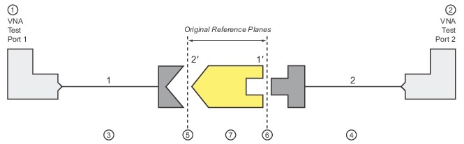
The concept of the adapter removal relies on the existence of two related sets of reference planes with one set on either side of the adapter (see Figure: Adapter Removal Block Diagram below). Assuming one can perform a full calibration at each set of reference planes, there is enough information to extract the behavior of the adapter itself. When the calibration is being performed at the reference planes on the left (between Ports 1 and 2’), the adapter behavior is embedded in the characteristics of Port 2’.
Similarly, when the calibration is being performed between Ports 1’ and 2, the adapter behavior is embedded in that of Port 1’. Since each of these two calibrations involve mating connector types, these are far easier to perform than the direct 1-2 calibration. It will not be shown here, but the use of the two calibrations provide nearly enough information to extract the parameters of the adapter itself. Figure: Adapter Removal Block Diagram shows the structure of the adapter removal calibration. Two calibrations are performed at the two sets of reference planes shown (between Ports 1 and 2’, and between 1’ and 2), which allows a determination of the adapter behavior. After the adapter removal, the resulting calibration will be between Ports 1 and 2.
Adapter Removal Block Diagram
1. Test Port 1
2. Test Port 2
3. Port 1 Test Cable
4. Port 2 Test Cable
5. Original Reference Plane 2’, when adapter is connected to Port 2 Test Cable
6. Original Reference Plane 1’, when adapter is connected to Port 1 Test Cable
7. Adapter to be calibrated
Caveats and Limitations
There are two caveats to this procedure.
First, only the S12S21 products of the adapter can be determined from this procedure, not the two transmission terms individually. However, since only the product is needed to de-embed the adapter effects, this is not much of a problem. Most adapters are passive and reciprocal anyway, so the individual terms could be determined if necessary.
Second, there is a complex square root operation involved, so a root determination is necessary. To help this, the user must enter a guess as to the electrical length of the adapter (in ps of delay). The guess need not be very accurate, just within the correct half plane. At 2 GHz, this means the error in delay entry should be less than 125 ps to ensure the correct root is selected.
In general the error must be less than where f is the highest frequency being used.
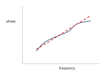
One can enter 0 for the length estimate to force the software to do length estimation internally. This calculation is based on the phase change between frequency points towards the lower end of the sweep range. A linear fit to the phase function is performed and the slope is used to estimate the electrical length as suggested by Figure: Auto Calculating Length Estimate Issues. This procedure is quite accurate unless the frequency step size is large relative to the phase change in the measurement. Thus, if the setup uses very long cables, it may help to increase the number of frequency points or at least look at a raw S21 phase display (no calibration applied with something of modest insertion loss connected) and see how often the phase wraps.
Auto Calculating Length Estimate Issues
By entering 0 as the length estimate, the software calculates a length estimate for you. If the frequency step size is large relative to the electrical length of the setup, this may not be advisable.
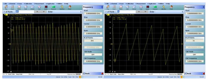
In Figure: Uncalibrated Phase Plot Examples, one can see how the first frequency step size would be adequate for this setup. The phase change between points is well below 180 degrees so linear fitting will not run into aliasing problems. In the second setup, the phase change between points is nearly 360 degrees so one may start to run into aliasing issues with the 0-entry-length-estimation. For this case, the point count should be increased at least somewhat or a manual length entry can still be used in Adapter Removal.
Uncalibrated Phase Plot Examples
Uncalibrated phase plots from an example setup are shown here for two different step sizes. In the second case, the automatic length estimation may run into aliasing problems if much more length is added.
 where
where