With reciprocal methods, the usual determining question is ‘how bad are the characteristics of a thru?’ in the environment in question. As suggested earlier, if the thru is good (RL~>25 dB and insertion loss known to within ~0.05 dB), then for most purposes, the defined thru methods will do better since there is a more explicit determination of load match. As the reciprocal device worsens in terms of insertion loss and match, the sensitivity of the calibration to small standards problems will increase because less and less information is available to the calibration. In this sense, sensitivity may be a more practical metric than best-obtainable uncertainty, which will be fairly similar in all cases.
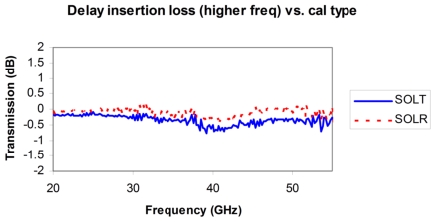
When the available thru is poor, however, then the absolute defined thru uncertainty will be high. In one example, delay insertion loss deviation was plotted for two calibrations (SOLT and SOLR) where the only interconnect available had 8 to 15 dB return loss across the band. The SOLT measurement shows almost 0.7 dB deviation (on a low loss device) while the SOLR deviation was kept to < 0.2 dB as shown in Figure: Example Comparison (Insertion Loss Deviation) Between SOLT and SOLR.
Example Comparison (Insertion Loss Deviation) Between SOLT and SOLR
An example comparison (insertion loss deviation) is shown here between SOLT and SOLR when no good thru connection was available.
There are limits on the reciprocal network, as discussed above, and those will become most apparent when measuring reflection of well-matched, low insertion loss devices. The one mitigating factor is that if the media is complicated enough to require a reciprocal technique, there will be fewer well-matched, low insertion loss devices to be concerned about. The issue becomes one where the resolution on load match during calibration becomes limited by the reciprocal itself, so the correction for that term will become more sensitive.
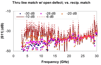
As an example, consider the match measurement of a delay line where a problem was introduced on the open standard during the calibration. A series of different calibrations were done with different reciprocal devices (with different match levels). The resultant measurements are shown in Figure: Plot of Sensitivity of Return Loss Measurements. For reciprocal elements with reasonable match (~< -20 dB), the measurements did not become distorted significantly by the open calibration error. At the -10 dB reciprocal match level, measurements below ~-20 dB were impacted. At the -6 dB reciprocal match level, even higher reflection measurements would have been distorted. A somewhat obvious guiding principle is that the reciprocal used for the calibration should not be worse (in terms of return loss or insertion loss) than the devices that will be measured with that resulting calibration.
Plot of Sensitivity of Return Loss Measurements
A plot of sensitivity of return loss measurements to a problem with one of the reflection standards is shown here for a variety of reciprocal devices used during the calibration.