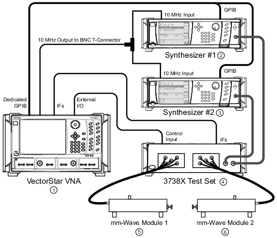
Broadband and mmWave modes are remote-control intensive, so much of the setup work revolves around setting up communication to the external synthesizers and the external test set (3738X). Of course, some care must be taken with the IF, RF and LO connections but the issues here are typically the usual ones of connector and cable care. The control and reference connections are illustrated in Figure: Broadband and mmWave Setup.
Broadband and mmWave Setup
1. VectorStar Series VNA
2. Synthesizer #1
3. Synthesizer #2
4. 3738X Test Set
5. mmWave Module 1
6. mmWave Module 2
Some things to point out:
• The IF cables from the 3738X test set to the MS464xB (both rear panel) are not shown here.
• The External I/O connector is used to supply simple control bits to the 3738X test set. These bits are level-sensitive only, asynchronous, and low speed and there is no addressing so this connection is relatively simple to administer.
• The synthesizers are synchronized to the 10 MHz reference of the MS464xB so frequency accuracy is maintained. External 10 MHz sources can also be used if they have at least the spectral purity of the VNA internal clock. For more information, see:
• MS464xB Series VNA Technical Data Sheet and Configuration Guide—11410-00611
• The cable bundles between the test set and the mmWave modules supply analog signals, bias and simple control information. Anritsu-supplied bundles should be used here in most cases.
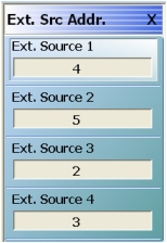
• The GPIB connections are used for controlling the synthesizers and usual GPIB cable length practices apply. Note that the “dedicated” connector on the VNA is used. The synthesizer GPIB addresses must match those on the VNA external source address menu (see Figure: EXT. SRC. ADDR. (EXTERNAL SOURCE ADDRESS) Menu below, the menu is located under in the SYSTEM menu group:
• MAIN | System | SYSTEM | Remote Interface | REMOTE INTER. | Ext. Sources | EXT. SRC ADDR.
EXT. SRC. ADDR. (EXTERNAL SOURCE ADDRESS) Menu
• Note that in broadband/mmWave mode, External Source 1 is defined as the LO and External Source 2 is defined as the RF. Ensure that the RF/LO connections between the synthesizers and the 3738X test set match this designation. If it is desired that other external sources be used, multiple source mode should be used instead of broadband/mmWave.
• For most mmWave modules, the synthesizers must have a maximum frequency of at least 20 GHz and a minimum frequency of no more than 2 GHz. For the control software to operate, the synthesizers must be from Anritsu.
• Normally the IF signals from the mmWave modules are routed through the 3738X test set (amplifiers and some switching) on their way to the rear panel of the MS464xB Series VNA. Depending on the setup, the IF signals can sometimes be routed directly to the VNA.
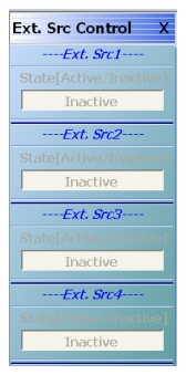
The system will poll the GPIB bus for the external synthesizers periodically including when the broadband/mmWave mode is activated and when its menus are accessed. If unsure if a connection has been established, check the EXTERNAL SOURCE CONTROL menu (under multiple source setup) to see if they are ACTIVE as in Figure: EXT. SRC. CONTROL (EXTERNAL SOURCE CONTROL) Menu. In broadband and mmWave modes, the External Sources 1 and External Sources 2 should be automatically activated if they are detected.
EXT. SRC. CONTROL (EXTERNAL SOURCE CONTROL) Menu
If one or both synthesizers are turned off or disconnected while in broadband or mmWave modes, GPIB errors or sluggish system response may be noted. It may be necessary to return to standard mode, reconnect/restart the synthesizers and then re-enter the broadband/mmWave mode to continue. In extreme circumstances, one may want to exit the VNA application, restart the synthesizers, and restart the VNA to establish communication.