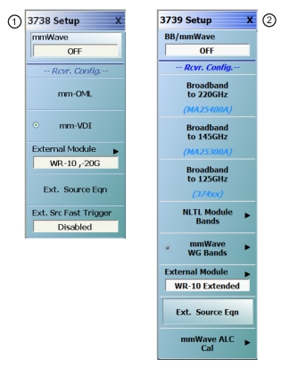
The BB/mmWave Setup selection brings up the menu shown in Figure: BB/mmWAVE Setup Menus. The On/Off toggle at the top duplicates, in some sense, the Rcvr Config selection in the middle of the APPLICATION menu (turning BB/mmWave OFF will change the selection to standard).
The Rcvr Config section on the SETUP menu provides the user broadband and mmWave selections. As stated above, the distinction involves whether the instrument will be allowed to couple sweeps of the internal VNA hardware with sweeps of the external modules.
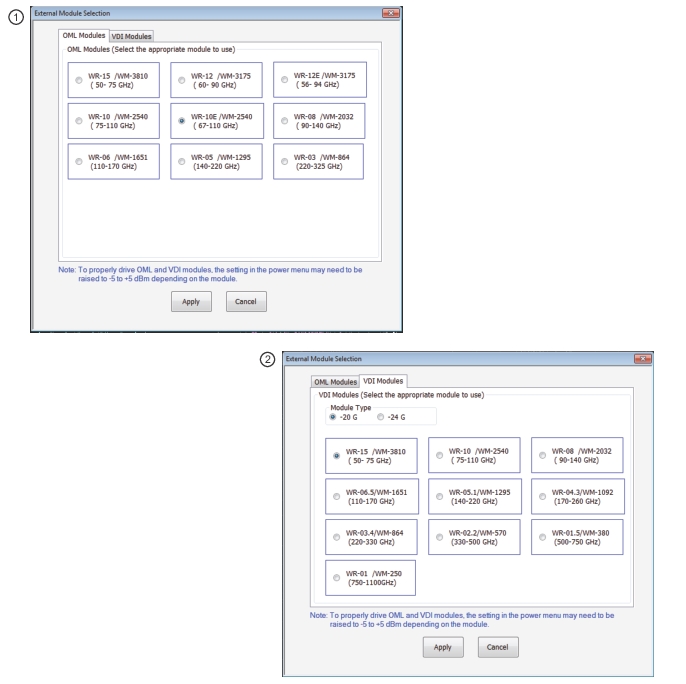
The external module selection, available only when the mode is mmWave (unavailable when in broadband mode), allows the selection of different module frequency ranges. This selection populates the frequency range and synthesizer control fields (harmonic number used for calculating synthesizer frequencies, etc.). These values can be overridden in the EXT. SOURCE EQUATION dialog or one can go to full manual control using multiple source. Selection of the External Module button displays tabbed dialog box with current waveguide selections as shown in Figure: EXTERNAL MODULE SELECTION Menu below.
EXTERNAL MODULE SELECTION Menu
1. At top, the OML tab is selected and the available OML Modules are shown. Select a module radio button to configure that module.
2. At bottom, the VDI tab is selected and the available VDI Modules are shown. Select a module radio button to configure that module. Note that VDI modules have two basic types at -20 G and -24 G. The module type selected here must match the module being used, as the two types have slightly different frequency plans.
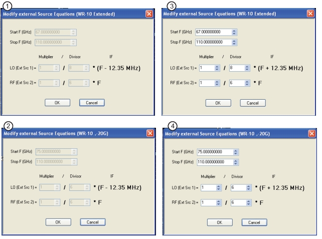
The EXTERNAL SOURCE EQUATION dialog displays the frequency ranges used by the module and the equations used to program the synthesizers. These values can be edited by the advanced user who wants to change the behavior of the modules or if new modules become available (not commonly used).
Note that the IF is fixed and un-editable in these dialogs (12.35 MHz). If more advanced adjustments of the frequency plan are desired, the user should go to multiple source mode.
To enable or disable fast trigger mode when using MG37xxxX external synthesizers, click on the Ext. Src. Fast Trigger button which will bring up the dialog. Select the desired mode (ensuring needed cables are connected) and click ok to effect the mode change.
Power control is possible by using the EXT SRC POWER menu for the RF source (Ext Src 2 listed above). It should be noted, however, that the multipliers used in the mmWave modules have extremely non-linear power in-power out transfer curves so the use of the input power (via the menu just referenced) as control can result in violent output power changes. In some firmware versions, an open-loop power calibration can be performed to simplify this task.
From a troubleshooting point-of-view, the most typical problems involve synthesizer communications (either GPIB or fast trigger). As discussed elsewhere, resetting or power cycling of the synthesizers may be required if no problems are found with the cabling or address settings. Sometimes RF and LO cables are swapped which can result in odd ripples in unratioed parameter displays (inappropriate power levels resulting from the swap).