The typical setup for the modular BB system is shown in Figure: System Setup for Modular BB Mode (1 of 2) below. In contrast to the classical BB/mmWave setup discussed previously, external synthesizers are not used but conditioned versions of internal VNA source and LO signals are instead routed to the modules. An option on the VNA (-08x) provides these connection points that the test set (3739x) uses for routing to the modules. Much like in the classical setup discussed before, control and power connections are provided by the test set to the modules and IF signals are taken from the modules for routing to the VNA. As with the classical mode, Option 7 (frequency offset) is required for the more elaborate frequency programming.
The 3739X operation with the MS464XX is controlled by the Options 8x mentioned above. These options are correlated with specific system designations and functionality but there is less correlation with which modules will be used. Table: Option 8x Descriptions may help explain this.
Two additional rear panel connections are used in this system: an external ALC connection is used between the test set and the VNA to enable leveled power control at the heads and the VNA external analog out function is used to assist in LO leveling. Note that when in Modular BB mode, the normal function of the Ext Analog Out connector is suspended.
When in Modular BB mode, the frequency plan calculations are automatically changed to account for the multiplier behavior and the allowed frequency ranges.
• For ME7838A/AX and related systems (using the 3743A/AX modules), the range is 70 kHz to 125 GHz if Option 70 is installed (10 MHz start frequency otherwise).
• For ME7838E/EX and related systems (using the 3743E/EX modules), the maximum frequency is 110 GHz.
• For ME7838D and related systems (using the MA25300A modules), the maximum frequency is 145 GHz.
• For ME7838G and related systems (using the MA25400A modules), the maximum frequency is 220 GHz (operational to 226 GHz).
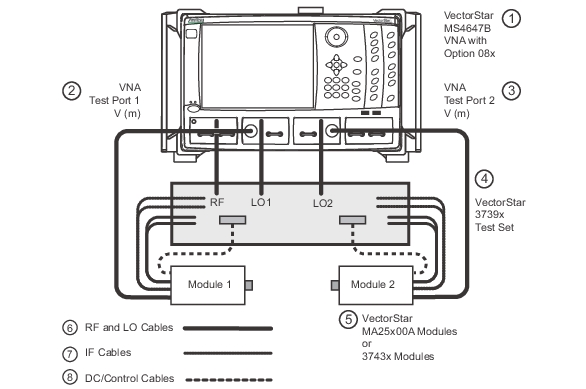
System Setup for Modular BB Mode (1 of 2)
The system setup for the modular BB mode is shown here. Rear panel connections are not shown. The shaded boxes on the modules denote the test port connectors. The VNA in this figure has Option 8x which provides the Src, LO1, and LO2 connectors shown in the figure.
1. MS4647B VNA with Option 8x
2. VNA Test Port 1 V (m)
3. VNA Test Port 2 V (m)
4. 3739x Test Set
5. MA25300A Modules, 2 each, or MA25400A modules, 2 each, or 3743A/AX/E/EX Modules, 2 each, or 3744A/E/EX-xx Modules, 2 each
6. Heavy lines are RF and LO Cables
7. Light dashed lines are IF Cables
8. Heavy dashed lines are DC/control cables
Option 8x Descriptions
Option
Description
080
For ME7838A/AX/ME7838D/ME7838G systems, used for single source VNAs (no Option 31) and no Option 051, 061, or 062 where broadband operation is desired (to 125 GHz/145 GHz/220 GHz with the appropriate modules).
081
For ME7838A/AX/ME7838D/ME7838G systems, used for single source VNAs (no Option 31) and with Option 051, 061, or 062 where broadband operation is desired (to 125 GHz/145 GHz/220 GHz with the appropriate modules).
082
For ME7838A/AX/ME7838D/ME7838G systems, used for single source VNAs (no Option 31) and no Option 051, 061, or 062 where only banded operation broadband operation is desired (E and W band).
083
For ME7838A/AX/ME7838D/ME7838G systems, used for single source VNAs (no Option 31) and with Option 051, 061, or 062 where only banded operation broadband operation is desired (E and W band).
084
For ME7838A/AX/ME7838D/ME7838G systems, used for dual source VNAs (with Option 31) and no Option 051, 061, or 062 (no distinction between banded and broadband in this case; operational to 125 GHz/145 GHz/220 GHz with the appropriate modules).
085
For ME7838A/AX/ME7838D/ME7838G systems, used for dual source VNAs (with Option 31) and with Option 051, 061, or 062 (no distinction between banded and broadband in this case; operational to 125 GHz/145 GHz/220 GHz with the appropriate modules).
086
For ME7838E/EX systems (using 3743E/EX modules), used for single source VNAs (no Option 31) and no Option 051, 061, or 062 (no distinction between banded and broadband in this case; operational to 110 GHz).
087
For ME7838E/EX systems (using 3743E/EX modules), used for single source VNAs (no Option 31) and with Option 051, 061, or 062 (no distinction between banded and broadband in this case; operational to 110 GHz).
088
For ME7838E/EX systems (using 3743E/EX modules), used for dual source VNAs (with Option 31) and no Option 051, 061, or 062 (no distinction between banded and broadband in this case; operational to 110 GHz).
089
For ME7838E/EX systems (using 3743E/EX modules), used for dual source VNAs (with Option 31) and with Option 051, 061, or 062 (no distinction between banded and broadband in this case; operational to 110 GHz).
In terms of completing the connections, the power/control cable ends at the module side with a snap-in microD connector. The two IF connectors are SSMC and the reference connector is closest to the middle of the module (this is also marked on the module). The V cable coming from the VNA port routes to the module V connector in the middle of the module. The K (LO) and V (Src) cables from the test set route to the appropriate outer connectors on the module. All coax connectors should be torqued properly.
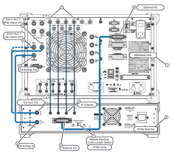
The rear panel connections are shown in Figure: Rear Panel Connections for the Modular BB System. Two BNC-terminated coax cables are used for routing Ext. ALC (External Automatic Level Control) and analog control signals between the test set and the VNA. A DB-25-terminated cable is used for routing digital control signals, and the IFs are routed using four SMA-terminated coax cables.
Rear Panel Connections for the Modular BB System
1. MS4647B VNA with Option 8x Rear Panel
2. 3739x Test Set Rear Panel
3. IF Input/Output Connections —VNA connections at top —Test Set connections at bottom.
4. External I/O Connections —VNA DB-25P at top —Test Set DB-25P at bottom.
5. External Analog Connections —VNA BNC at top —Test Set BNC at bottom.
6. External Automatic Level Control Connections —VNA BNC at top—Test Set BNC at bottom. — Ext In ALC 1 (without Option 31) — Ext In ALC 2 (with Option 31)
A block diagram of the system is shown in Figure: Modular BB Block Diagram below. The 3739x test set provides several distinct functions:
• Source power amplification and transfer switching
• LO leveling and distribution
• Generating control signals for the modules from VNA input and supplying power
• Routing and processing IF signals as necessary
The 3739x test set includes higher power amplifiers and further LO condition circuits for use with higher millimeter wave bands. The B model also includes an AUX POWER connector for a third module. This connector supplies power to the module and mimics the control signals sent to the Port 1 module. This makes the port very useful for IMD and mixer measurements. The second tone (for IMD) or the LO (for millimeter wave mixers requiring a high frequency LO) can be supplied this way. The second tone for these applications could be supplied by an external synthesizer (see multiple source in Multiple Source Control (Option 7)) or the optional second source in the VNA itself (see Dual Source and DifferentialView™ (Option 31 and Option 43)).
The modules themselves have several unique aspects:
• A bypass path for use at low frequencies. The internal VNA source and couplers/bridges are used for lower frequency measurements.
• At higher frequencies, separate reflectometers in the module handle the measurements.
• Also at higher frequencies, multipliers in the modules provide source power.
• Leveling circuitry (both source and LO) is built into the modules.
There are two main breakpoint frequencies that are helpful in understanding the performance of the system:
• The break where the module receivers take over from the internal VNA receivers. This is nominally at 30 GHz.
• The break where the module source multipliers take over for the main VNA multipliers. This is nominally at 54 GHz.
As with the classical approach discussed previously, this mode can also be invoked from within multiple source control for a more customized setup. Details of this approach are covered in Multiple Source Control (Option 7).
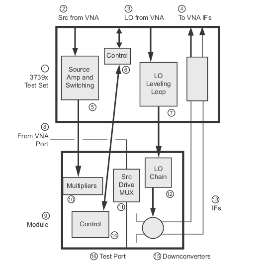
Modular BB Block Diagram
The modular BB block diagram is shown above. Relative to the classical setup, the MUXing is performed in a different location and different multiplier and downconverter technologies are used.
1. 3739x Test Set
2. Src from VNA
3. LO from VNA
4. To VNA IFs
5. Source Amp and Switching
6. Control
7. LO Leveling Loop
8. From VNA Port
9. MA25400A, MA25300A, or 3743x Module
10. Multipliers
11. Src Drive MUX
12. LO Chain
13. IFs to Test Set
14. Control
15. Downconverters
16. Test Port
Full power control and power sweeps are available in this mode due to the integrated leveling circuitry in the modules and test set. Flat power calibrations/linear power calibrations are also available and function as described in other chapters. An important point is that the standard Anritsu power meters are used up to 70 GHz while separate waveguide-based power meters are needed above 70 GHz. Normally an Agilent W8486A W-band sensor or equivalent is used for 70 GHz-125 GHz (for ME7838A/AX and ME7838E/EX and related systems, only used to 110 GHz for the E/EX systems) and an Elva -1 power meter with D-band sensor is used for frequencies of 125 to 170 GHz (for ME7838D/ME7838G and related systems). For frequencies above 170 GHz (ME7838G and related systems), an Elva-1 power meter with a G-band sensor is used. For traceability and accuracy information, contact the factory. The calibration routines will prompt when a different meter/sensor needs to be connected. Because of the need for adapters in many cases, the manual power offset feature may be employed on the power meters to correct for adapter loss (e.g., a W1-WR10 coax-to-waveguide adapter typically has 0.5 dB of loss at 110 GHz).
Full ALC calibrations are performed at the diagnostics menu level of the firmware and are normally only employed in service situations. When moving between Standard and Modular BB modes, the ALC calibration files automatically switch to properly handle the hardware being used in those modes.
From a troubleshooting point-of-view, miscabling of the system is the most common problem. A typical symptom is non-ratioed parameters that are very low (< – 90 dB; when at default power, a1/1 and a2/1 will typically be in the –10 to –30 dB range (uncalibrated) depending on frequency). Very low received signals can sometimes also be due to requesting a leveled power too far below specified ranges (the system will allow lower entries than specified since they may be achieved at certain frequencies).
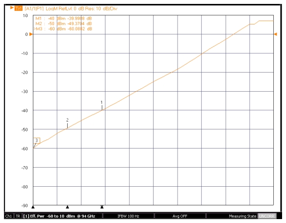
The normal ALC range when above 54 GHz reaches down to -60 dBm, although there may be some significant drop-offs below –55 dBm (and below –50 dBm above 110 GHz for those systems operating to higher frequencies). This is possible because of the highly linear integrated UIF leveling loop based within the modules. A separate RF leveling loop is also available for frequency translating measurements (discussed in Multiple Source Control (Option 7)). Because no step attenuators are in the mmWave part of the system, this extended ALC range is particularly useful. Since the power structures are fairly different above and below 54 GHz (with or without step attenuator possibilities), two different ALC entries are used and are labeled as such on the Power menu. An example of the wide power range and wide power sweep range is shown in Figure: Example of Wide Power Sweep Range Available with the Modular BB System. (the curve flat lines at the upper end of the sweep as it reaches maximum power of ~+3 dBm for this frequency). To achieve a constant low power level in a broadband sweep, it will be necessary to use step attenuators below 54 GHz and a low base setting above 54 GHz.
Example of Wide Power Sweep Range Available with the Modular BB System.
Example:
• Broadband sweep with port power of -50 dBm
• Set the ALC level (<54 GHz) to -20 dBm and engage 30 dB of source step attenuation (assumes Option 061 or 062)
• Set the ALC level (>54 GHz) to -50 dBm
User power calibrations can be challenging with the broadband systems at lower power levels since most of the available sensors have limited dynamic range (often –25 dBm as a practical lower limit). To get around this issue, the system automatically uses a different approach when the requested power level is below –25 dBm:
• The requested power is set to –20 dBm and a power measurement is taken with the appropriate power meter. At the same setting, a measurement is made by the ax receiver (the reference signal where x represents the current driving port). This is an internal re-referencing step where the power meter accuracy is transferred to the receiver. Since the instrument receivers are very linear (to within 0.01 dB down to levels only limited by the system noise floor), this is an efficient transfer process to allow for low level calibrations.
• The system is then set to the target power level and an ax measurement is made and this is converted to port power based on the above re-referencing. The search process then proceeds as usual to get the re-referenced power to the desired target.
• This process is repeated for each frequency and power (depending on sweep mode) for power levels below –25 dBm.
Anritsu PowerMaster frequency-selective power sensors also have extended dynamic range since they use a downconversion process instead of thermal sensing for power measurement. The frequency selective power meters can be used for slightly lower power levels (but generally not less than about -35 dBm).
An added tool to assist in power calibrations is the ability to embed or de-embed .s2p files describing networks added after the power calibration. One example of this is moving the power reference plane from the connector or flange interface to the end of a probe tip.