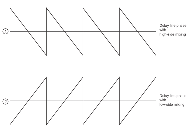
1. Delay line phase with high-side mixing (at top).
2. Delay line phase with low-side mixing (at bottom).
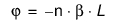
The selection of the phase inversion button reverses the effect seen in low side mixing. The most severe impact can occur in calibrations where line and offset lengths are presumed to impact phase according to equations like (where L is the length and B is the propagation constant):
Equation 18‑2.
If low side mixing is present, the sign of this equation is incorrect and the calibrations will proceed with the wrong phase values. Proper selection of the phase inversion button will avoid those problems.
The phase inversion feature is not available in 'simple' mode, but the state will be retained for when one returns to 'complete' mode.
Receiver Source and Receiver Calibrations
Although receiver calibrations are covered in more detail in another section of this measurement guide, the special use of a multiple source equation should be discussed here.
The receiver calibration is sufficiently general that it may help perform power normalizations even at the plane of an external converter (acting like a pre-receiver). This receiver may be well-characterized at its frequency range (different from the frequency range of the MS464xB Series VNA receiver) but there must be some means of looking up the correct value in that characterization. This is the purpose of the receiver source equation: to act as an index to a receiver calibration that may refer to an unusual reference plane. In most common cases, the receiver source equation is just set equal to the receiver equation. If receiver calibrations are not in use, this equation can be set to any valid frequency.