The key concepts to setting up multiple source control are:
Four External Sources for MS464xB VNAs
For MS464xB Series VNAs, up to four (4) external sources can be configured.
Frequency Plan Bands
The frequency plan is separated into “bands”. There may be as many as 50 or as few as one. One needs multiple bands ONLY if the relationship between sources and the receiver change in an unusual way at some point in the sweep. Examples:
• A mixer measurement is being set up where the RF and LO are offset by a fixed amount and the IF (which will be sent to the VNA receiver) is constant. Only one band is needed.
• A harmonic converter is being tested where it operates on the 2nd harmonic of the LO up to 10 GHz and the 3rd harmonic beyond that. Two bands are needed here.
• The 'simple' mode is restricted to one band.
Linearly Linked Source Frequencies
All source frequencies (internal or external) and the receiver frequency must be linearly related. All are expressed as linear equations as a function of a runner variable “f”. This variable f is always the one displayed on the X-Axis although it need not represent an actual frequency (although for convenience it usually does).
These linear relationships can change in different “bands” that the user defines. The band edges are always in terms of the runner variable f.
Band Start Frequency, Band Stop Frequency, and Runner Variable f
The band start and stop frequencies are in terms of the runner variable f. Thus they may or may not be physical. To reiterate, the choice is usually based on what one wants the X-Axis of the plots to be labeled in terms of, for example, the RF frequency or the IF frequency for a mixer measurement.
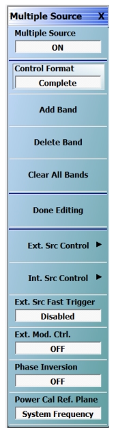
Main MULTIPLE SOURCE Setup Menu in its ‘Complete’ form. The ‘Simple’ form does not have the band elements, or some of the other features.
The MULTIPLE SOURCE menu appearance differs slightly depending on the instrument model number, installed options, and band edit state.
In this case:
Multiple Source is set to OFF. Toggling Multiple Source here also changes the Rcvr Config selection on the APPLICATION menu.
Mixer Mode is set to ON.
External Source Fast Trigger set to Enabled.
External Module Ctrl. set to OFF.
Phase Inversion set to OFF.
Power Cal Ref. Plane is set to SYSTEM FREQUENCY. Select toggles the Power Cal Reference Plane between System Frequency and Source Equation. For more information, see Power Calibration Reference Plane
The top button on the menu toggles Multiple Source mode on or off, similar to the mode selection buttons on the APPLICATION menu (turning Multiple Source mode off here will change the Receiver Config mode on the APPLICATION menu to Standard). When the MULTIPLE SOURCE menu is entered, the MULTIPLE SOURCE tableau will appear in the lower part of the screen (Figure: MULTIPLE SOURCE Tableau below).
Note
The Done Editing button MUST be clicked for new values to take effect.
Band frequency ranges DO NOT define a required start and stop frequency. These merely set the min and max possible for start and stop. Readjust the desired range for actual measurements on the frequency menu.
When the MULTIPLE SOURCE tableau first appears, the first band is in the table. The Add Band, Delete Band, and Clear Band buttons will have the obvious effects.
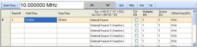
MULTIPLE SOURCE Tableau
The MULTIPLE SOURCE tableau dialog appearance differs slightly depending on the instrument model number and installed options.
Defining a Multiple Source Band
A red exclamation point (!) in the first column of the table indicates that an error is detected.
For each band, the following must be defined:
• A start frequency for the band.
• A stop frequency for the band.
• Equations for each source, the receiver, and receiver source (an index used to work with receiver calibrations). If a source is inactive, its equation may be left at anything. If active, the result of the equation must be a valid frequency for that source (or receiver).
Each equation is of the following form:
Equation 18‑1.
Using the multiplier (M) and divisor (D), a rational relationship can be created between the desired frequencies. The offset (OS) completes the remainder of the linear relationship and is the CW frequency when the source is set to CW ON. Any of these parameters may be negative as long as the result of the equation is a valid frequency for that source (or receiver). This can be used for a reverse sweep (in certain mixer measurements for example).
When a cell is highlighted in the table (with the mouse or touch screen), the text entry box becomes active. Text can be directly entered into the table by double-clicking on the cell. The entry must be typed with a space between the number and the frequency units.
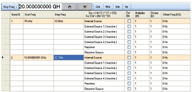
MULTIPLE SOURCE Tableau—Two Band Multiple Source Tableau
The MULTIPLE SOURCE tableau dialog appearance differs slightly depending on the instrument model number and installed options.
As soon as values are changed in the table, the Done Editing button shown in Figure: Main MULTIPLE SOURCE Setup Menu in its ‘Complete’ form. The ‘Simple’ form does not have the band elements, or some of the other features. becomes active. Selecting the Done Editing button will start an error check of all entered parameters. An error dialog may appear if an error is found. During the error checking, the system applies the band limit frequencies to each equation and checks that the results are valid for a given source or the receiver. If an external source is inactive, the error checking will not be performed for that line.
Note
The Done Editing button in the Multiple Source menu MUST be clicked for new values to take effect.
Band frequency ranges DO NOT define a required start and stop frequency. These merely set the min and max possible for start and stop. Readjust the desired range for actual measurements on the frequency menu.
External Module Control
The EXTERNAL MODULE dialog box is accessed off the MULTIPLE SOURCE menu.
This dialog box allows the use of a 3738x or 3739x Test Set and external broadband or millimeter-wave modules. The activation is by band and when turned on, the test set will be informed to activate its modules and use current knowledge of the driving port. This would commonly be used for broadband or mmWave measurements when the broadband/mmWave mode is too restrictive for the desired measurements. This may happen if different IFs are desired, additional frequency converters are involved in the measurement, or other unusual scenarios. The external IF ports are automatically activated in any of the non-Off modes, as are leveling and power control schemes associated with the given test set (see Broadband/mmWave Measurements (Option 7, Option 8x) for more test set information). Only one global mode can be selected per channel but that external module selection can be activated or de-activated on a band-by-band basis.
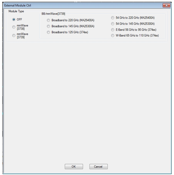
External Module Ctrl = OFF
External mmWave or broadband test sets are not being used. The dialog in this state is shown in Figure: External Module Control Dialog Box with OFF Selected. The 3739x test set does not require external synthesizers, so these non-OFF choices will always be available assuming Option 8x is present. The 3738 test set does not require additional options, but does require the presence of external synthesizers 1 and 2 on the GPIB bus.
External Module Control Dialog Box with OFF Selected
External Module Ctrl = mmWave (3738)
The 3738x test set is being used with conventional OEM mmWave modules (the ME7828 family of systems). In this case, a check box will be available per-defined band to allow activation of the test set in that band. This option is only available if External Sources 1 and 2 are connected and active. There are no other parameters to select other than to activate or de-activate on a band-by-band basis.
As an example to show how this selection might be used, consider a DUT that is a downconverter taking 250 to 300 GHz down to a fixed IF of 1 GHz. The LO is sub-harmonically driven with an effective multiplier of 18 and will be driven from External Source 3 (EXT. SRC 3). The RF is supplied by an external mmWave module (WR-03 waveguide in this case), which also has an effective source multiplier of 18, and this will be driven from External Source 1 (EXT. SRC. 1). This external module also has an LO input (x20 effective multiplier) that will be driven from External Source 2 (EXT SRC 2). It is desired to measure both return loss (at the RF) of the DUT as well as its conversion loss. This will require two different multiple source setups since the conversion paths in the VNA are different.
Return Loss Measurement
Connect all external synthesizers and make sure the GPIB addresses match, and that 10 MHz clocks are synchronized (or higher frequency references if those are being used). It is desired that the DUT LO port be driven since that can affect return loss. Since the mmWave module IF outputs will be used (and routed to the VNA rear panel), Ext Module Ctrl for BB/mmWave must be enabled.
• Band 1: 250-300 GHz
• Int Src (Internal Source) = 1/1(CW 3 GHz)
• We are not using the internal source so it is just parked.
• Ext Src1 (External Source) = 1/18(f +0)
• Ext Src2 = 1/20(f+12.35 MHz)
• The system IF (rear panel) is 12.35 MHz.
• Ext Src3 = 1/18(f+ 1 GHz)
• Rcvr (Receiver) = 1/1(CW 2 GHz)
• We are not using the internal LO so it is just parked.
Conversion Loss Measurement
In this case, Ext Module Ctrl must be OFF since we will not be using the rear panel IFs. Note that this also disables the test set so some care is required with RF signal cabling.
• Band 1: 250 to 300 GHz
• Int Src = 1/1(CW 3 GHz)
• We are not using the internal source so it is just parked.
• Ext Src1 = 1/18(f +0)
• Ext Src2 = 1/1 (CW 2 GHz)
• The external mmWave module LO is not being used.
• Ext Src3 = 1/18(f+ 1 GHz)
• Rcvr = 1/1(CW 1 GHz)
• The DUT IF is routed to a port or receiver loop so it can be converted.
External Module Ctrl = mmWave (3739)
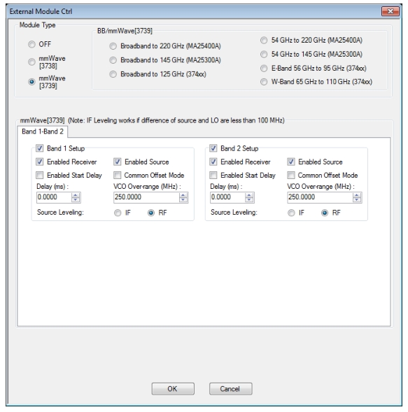
The mmWave (3739) selection also assumes the use of OEM mmWave modules, but with the 3739x test set. Details on some applicable modules, from a hardware perspective, are discussed in Broadband/mmWave Measurements (Option 7, Option 8x). Any multiplied transceivers can be used here as long as the frequency and power plans are consistent with the VectorStar system with the 3739x test set. The test set offers additional power control options and assumes the use of the internal VNA sources so there are some additional selection options as suggested by Figure: External Module Control Dialog as Configured for a Single Active Band of mmWave (3739). Note that as additional bands are added to the multiple source definition, the band check boxes must be manually checked for each in this EXTERNAL MODULE CTRL dialog.
External Module Control Dialog as Configured for a Single Active Band of mmWave (3739)
The selection choices per band are described below:
• Enabled Receiver: Use the receiver in the remote modules. Above this breakpoint, the VNA system LO will be set appropriately in terms of frequency and power, the test set configured, and the VNA’s rear panel IFs will be activated.
• Enabled Source: Use the source multipliers in the remote modules. When enabled the VNA synthesizers will be set appropriately, the test set configured as needed, and ALC leveling prepared (see below).
• Enabled Start Delay: This enables a fixed delay at the beginning of the band. This could be useful for certain slow settling DUT measurements or for very low power levels.
• Common Offset Mode: At higher multiples (generally for modules running over 300 GHz), it may be desired to improve source correlation to reduce trace noise. This can be done with the Common Offset mode bit (and it is automatically done in the 3739 mmWave modes discussed in Broadband/mmWave Measurements (Option 7, Option 8x)). If the source and receiver frequencies (when reduced to the 2.5-5 GHz range by division) differ by more than about 50 MHz with this bit selected, phase lock errors may occur so this selection is not appropriate for mmWave mixer measurements but is useful for IMD and other related measurements.
• VCO Over range: Normally, the internal VNA multipliers switch at 5, 10, 20, and 40 GHz. In some mmWave modules operating with high multipliers, it may be desirable to push those switch points out further (up to 5.5, 11, 22, and 44 GHz typical, but not guaranteed). This overrange (expressed in MHz relative to the 5 GHz breakpoint) sets the new breakpoints.
• Source Leveling: The leveling choice determines which detection path is used (RF implies the VNA detection on the RF drive path, IF uses the test set detection on a reference IF). Additional cals using the mmWave ALC subsystem may be required. Generally, IF leveling is only valid if the IF coming from the mmWave modules is under 100 MHz.
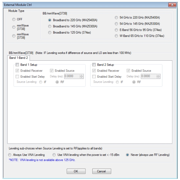
External Module Ctrl= BB/mmWave (3739)
For use with 374xx and MA25300A/MA25400A modular components. This right side of the radio button array is for the broadband operation and for banded operation. The selection for BB/mmWave is straightforward. When checked in a given band, the test set will be activated, the VNA’s internal transfer switch will be shut down, and the rear panel IF ports on the VNA will be activated. There are choices for broadband and banded operation. The distinction between these selections is based on the imposed frequency range limits when activated. Broadband allows from the lower instrument limit up to the upper limit of the system (110 GHz, 125 GHz, 145 GHz (150 GHz operational), or 220 GHz (226 GHz operational) for ME7838E/EX, A/AX, D, and G systems respectively), E band allows 56-95 GHz (under-range to 54.000000001 GHz allowed) using 3743x modules, and W band allows 65 GHz to 110 GHz using 3743x modules. For systems loaded with Option 80/081/084/085, three broadband buttons will be available for 125 GHz, 145 GHz (operational to 150 GHz), or 220 GHz (operational to 226 GHz) situations. Not all of the selections make sense depending on which modules are in use (e.g., if 3743A/AX modules are being used, only the first selection is useful). For ME7838E/EX systems (using Options 86/87) only operation to 110 GHz is allowed. Otherwise, the selections and instrument operation are the same. The dialog in the case of broadband set for two bands is shown in Figure: External Module Ctrl Broadband Mode (3739x-based) with Two Bands Configured. Note that as additional bands are added to the multiple source definition, the band checkboxes in this External Module Ctrl dialog must be manually checked.
External Module Ctrl Broadband Mode (3739x-based) with Two Bands Configured
These MA25x00A, 3743x, and 3744x modules have independent source and receiver paths that can be selected from the above dialog. The selections can be interpreted as follows:
• Enabled Receiver: Use the receiver in the remote modules above the receiver breakpoint (30 GHz). Above this breakpoint, the VNA system LO will be set appropriately in terms of frequency and power, the test set configured, and the VNA’s rear panel IFs will be activated.
• Enabled Source: Use the source multipliers in the remote modules above the source breakpoints (54, 80, and 120 GHz for x2, x3, and x4 respectively for 3743A/AX modules; 54 and 80 GHz for x2 and x3 for 3743E/EX modules; 54, 80, and 110 GHz for x2, x3, x6 for MA25300A modules); 54, 80, 110, and 150 GHz for x2, x3, x6 and x12 for MA25400A modules. Above the first breakpoint, the VNA synthesizers will be set appropriately, the test set configured as needed, and ALC leveling prepared (see below). Note that the above and below 54 GHz power control settings apply when this source feature is enabled.
• Enabled Start Delay: This enables a fixed delay at the beginning of the band. This could be useful for certain slow settling DUT measurements or for very low power levels.
• Source Leveling: The default operation of the modular BB system (when not in multiple source) is to use IF leveling in order to get wide power ranges, but if the source and receiver frequencies are not close enough (or the receiver is not enabled), then an IF is not available for leveling. The leveling defaults to RF in multiple source modular BB and this is recommended unless one knows the IF will be available (up to about 100 MHz) in the module for leveling. Separate ALC calibrations are available for RF and IF leveling and the system will automatically index the correct calibration table.
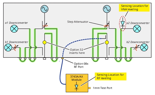
For RF leveling, there is an additional global choice (for dual-source, Option 31 instruments) for all bands < 125 GHz and with RF leveling selected: RF or VNA plane selection. The RF selection uses the detector in the mmWave module which has stability advantages since it is later in the chain but has limited dynamic range (–25 dBm to –20 dBm lower limit commonly). The VNA selection uses a detector in the host VNA which has the advantage of improved dynamic range (can usually reach –35 dBm to –40 dBm) but slightly reduced stability since the detection plane is behind some gain stages. Another selection is to automatically use VNA leveling for requested power levels below –15 dBm and RF leveling for higher levels. The default is RF leveling. The location of the leveling positions is sketched in Figure: RF and VNA Leveling Locations. Note that the VNA leveling sub-choice is not available for single-source instruments.
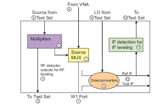
RF and VNA Leveling Locations
The RF and VNA leveling locations when in the broadband/mmWave (3739) mode are shown here for the case of a dual-source (Option 31) instrument. VNA leveling is not available for this mode in single-source instruments.
In the BB/mmWave receiver configuration of multiple source when the instrument has two sources, there are a number of additional measurement combinations possible including manual IMD (exclusive of Option 44), mixer measurements, desense measurements, and others. There are, however, some intricacies that warrant further discussion.
Key Point: In dual source systems operating as 2-port instruments, source 2 always drives the mmWave test set (true for pure mmWave 3739 modes as well).
As such, source 1 is the free source to act as drive for a 3rd module, to act as a subharmonic LO, etc. The source 2 equation state value will determine the test set state (assuming the corresponding box has been checked) and >54 GHz power control values will affect the 3739 test set drive for BB/mmWave when in the appropriate frequency range. The port 1 <54 GHz power control field will always affect source 1 drive (available from the VNA port 1 or the access loops if so equipped) and the label for that power field will change (Src1 to Aux Module). Note also that both sources must manually be made active (under Int. Src. Control) if it is desired that they drive simultaneously.
When both sources of Option 31 are active in a mmWave configuration (using this auxiliary module for source 1), power calibrations will be more complex. When in this state (multiple source with both sources active, one of the mmWave Ext. Mod. Ctrl. buttons clicked and in a mmWave frequency range), the power menu will have ‘Src1 driving aux module’ for the first field and the power calibration selector will have three choices (Port 1, Port 2 and Aux Module) in a 2-port system. The Target Power and other concepts are similar in all cases except the Aux Module calibration does not have a factory calibration as a starting point. At this stage the power associated with the Aux module is referencing the Port 1 test port of the baseband VNA. Because the output power of the module has a large offset from the VNA test port power it may take longer to converge and one may have to adjust the main power menu setting to get closer to the desired target. When one of these power calibrations is performed, the unindicated source will be deactivated so that unindicated source will not interfere with the calibration (if it, for example, was connected into the power measurement path via a combiner that was used for an intermodulation distortion measurement). After the calibration is complete, the sources are returned to their desired driving state.
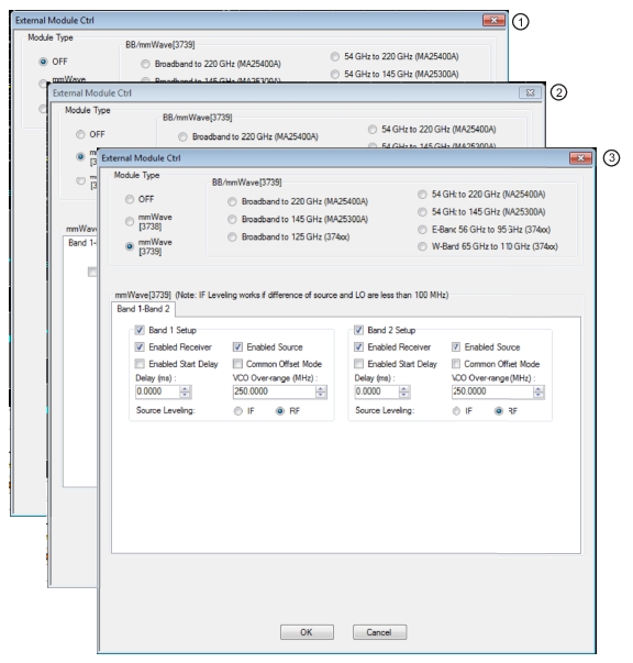
2. Dialog box with Module Type mmWave (3738) selected. Selection boxes enable Band 1 and/or 2.
3. Dialog box with Module Type mmWave (3739) selected. Selection boxes and control fields enable configuration control of Band 1 and/or Band 2.
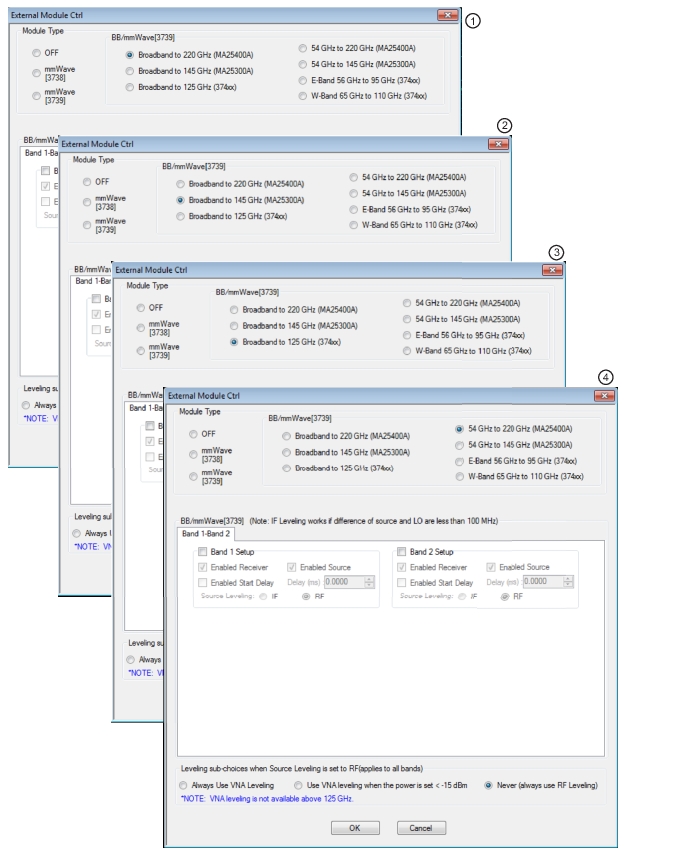
EXTERNAL MODULE CTRL Dialog Box—Broadband (1 of 2)
1. Dialog box with Module Type Broadband to 220 GHz selected. Selection boxes and control fields enable configuration control of Band 1 and/or Band 2. This module type and mode only available with MS4647B VNAs equipped with Option 8x.
2. Dialog box with Module Type Broadband to 145 GHz selected. Selection boxes and control fields enable configuration control of Band 1 and/or Band 2. This module type and mode only available with MS4647B VNAs equipped with Option 80/81.
3. Dialog box with Module Type Broadband to 125 GHz selected. Selection boxes and control fields enable configuration control of Band 1 and/or Band 2. This module type and mode only available with MS4647B VNAs equipped with Option 80/81.
4. Dialog box with Module Type 54 GHz to 220 GHz selected. Selection boxes and control fields enable configuration control of Band 1 and/or Band 2. This module type and mode is available with MS464xB VNAs equipped with Option 8x.
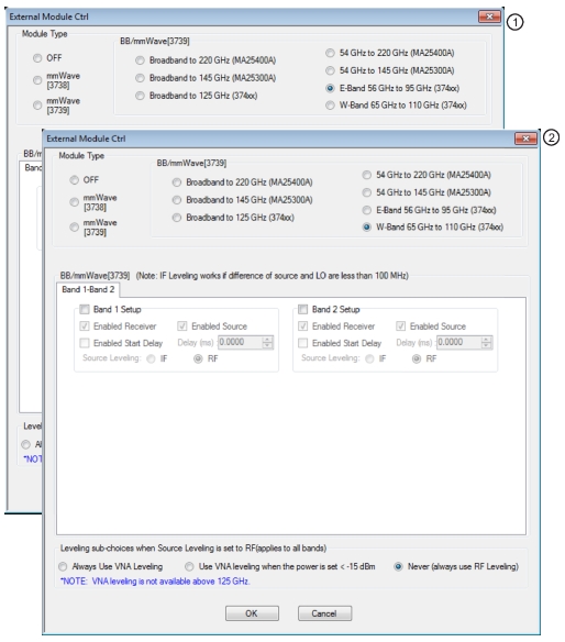
EXTERNAL MODULE CTRL Dialog Box—E-Band and W-Band
1. Dialog box with Module Type E-Band 56 GHz to 95 GHz selected. Selection boxes and control fields enable configuration control of Band 1 and/or Band 2. This module type and mode only available with VNAs equipped with Options 80/81 or 82/83.
2. Dialog box with Module Type W-Band 65 GHz to 110 GHz selected. Selection boxes and control fields enable configuration control of Band 1 and/or Band 2. This module type and mode only available with VNAs equipped with Option 80/81 or 82/83.
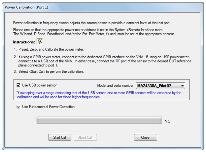
When in a broadband or mmWave version of modular 3739 modes, power calibration can be an important topic as these modes are frequently used for pseudo-absolute power measurements such a multiplier or mixer conversion, harmonics or IMD. Since the mmWave module can only have limited internal filtering of its source chain, the internal source harmonics can sometimes be relatively high (on the order of –10 dBc at some frequencies). Since the power meter used for the power calibrations can be sensitive to this harmonic energy but the tuned response of the VNA is not, there can be a disconnect between integrated and fundamental power that can impact measurement accuracy.
A function, known as fundamental power correction, is available as part of the user power calibrations in these modes that adjusts the power calibration to take into account these differences related to spectral composition of the source signal. When enabled (by the checkbox as shown in Figure: Fundamental Power Correction Checkbox in Power Calibration Dialog—(Appears Only in Modular Broadband or Banded mmWave Mode); this checkbox is only visible when in modular mmWave/Broadband modes), the user power calibration appears to proceed the same as always but, behind the scenes, the system receiver is used to estimate source harmonic levels (at each calibration frequency and/or power) and adjust the target power to take those contributions into account. When the calibration is finished, if one goes back with the power meter to check readings, they may appear high (e.g., the target value entered was –10 dBm but the power meter now reads –9 dBm at a calibration frequency) but this is because the calibration is now trying to get fundamental power to the target rather than integrated power.
Fundamental Power Correction Checkbox in Power Calibration Dialog—(Appears Only in Modular Broadband or Banded mmWave Mode)
Because of the extensive bookkeeping of receiver frequency plans needed for this process, the fundamental power correction is only available if the multiple source definition includes only one band. The correction only applies when the module is sourcing power (above the sourcing breakpoint frequency which is 54 GHz by default but can be changed with the configuration file as described elsewhere).
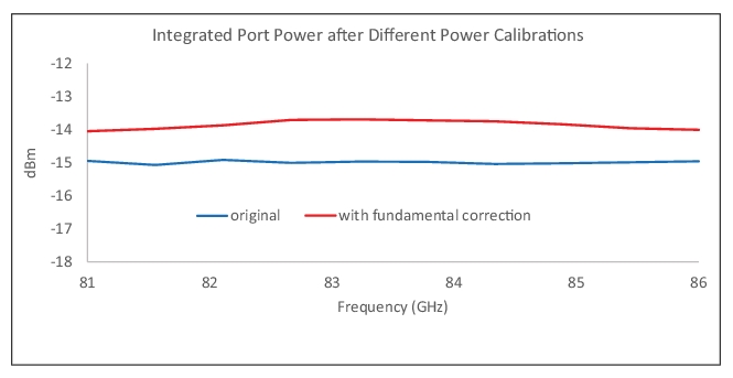
As an example, consider a power calibration over the range 81 GHz to 86 GHz and with a target power of –15 dBm using 3739 modular broadband mode. If one performs a standard power calibration, the power meter, after calibration, will generally measure quite close to –15 dBm (subject to drift, connector repeatability, etc.). In this case, however, source harmonics ranged from about –20 dBc at the edges of the range to about –15 dBc in the middle of the range. This leads the fundamental power (using the basic power calibration) being about 0.9 dB to 1.3 dB lower than the target value. By applying the fundamental power correction, the fundamental power is closer to target (which will make the VNA measurements more accurate) but the power meter will read a slightly higher value since it is measuring the fundamental plus the harmonics. The plot in Figure: Fundamental Power Correction Checkbox in Power Calibration Dialog—(Appears Only in Modular Broadband or Banded mmWave Mode) shows the difference in power meter readings after the calibration for the two different calibration choices. The fundamental power correction adjusts the integrated power target higher to get the fundamental power closer to the desired target value. In this case example, the target was –15 dBm and the harmonics were in the –15 dBc to –20 dBc range.
Integrated Port Power Calibration Comparison—with and without Fundamental Power Correction
External Module Control and Antenna Applications
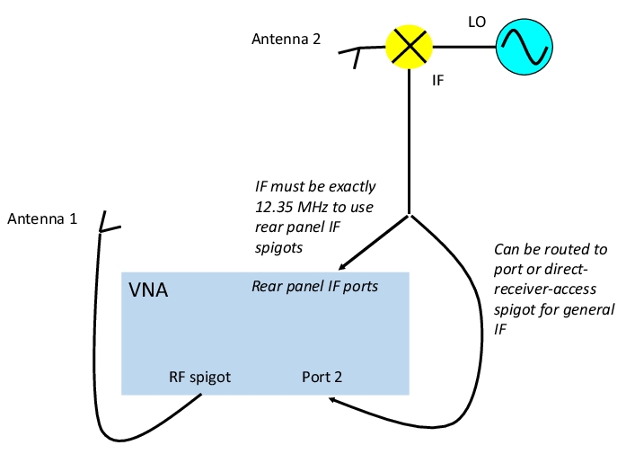
Although the labeling may not be obvious, External module control= mmWave (3739) can also be used for a variety of remote antenna measurement applications even if in the microwave band. In these applications, an external downconverter (often at a measuring antenna mount) is used to allow the measured signal to be sent long distances back to the VNA at a lower frequency. This structure is pictured in Figure: Example: Remote Antenna Measurement. The IF of this remote downconversion process can be at any VNA-accessible frequency and it can be routed to a VNA port (or a receiver direct access port on instruments with option 51, 61 or 62) for final downconversion by the VNA. In this case, External Module Control is NOT used. The LO for the external conversion can be from an external synthesizer or routed from the VNA (if option 31 is installed-the second source) and can be configured using standard multiple source control. Also the receiver equation can be set to look at the external IF frequency generated by the remote downconverter. If the internal source(s) is(are) used, they are available from the standard ports (or direct loop access, if so equipped) and option 08x is not required.
Example: Remote Antenna Measurement
Downconversion is done at the receiving antenna (which may be far away) to reduce the effect of cable losses. The IF from this downconversion can be routed to a VNA port or direct-access-receiver port in the general case (where the VNA will again downconvert to reach its internal IF) or could be routed to the rear panel IF spigots if already at the internal VNA IF of 12.35 MHz. For the latter case, external module control (and option 08x) is required.
Alternatively, if the remote downconverter can be set to produce an IF at 12.35 MHz (the VNA internal IF in most cases) and the instrument has option 08x, the remote IF can be routed directly to the rear panel IF ports that are normally used for the mmWave applications discussed in previous sections. Such a direct IF injection can provide noise advantages since an internal downconversion is omitted.
The mmWave (3739) External Module Control selection is important in that it enables the rear panel IF ports while imposing minimal other constraints on the frequency plan (unlike the broadband and E/W-band selections on that dialog). The internal sources can be used up to 40 GHz (for a MS4644B or MS4647B, 20 GHz for a MS4642B) while external sources can be controlled over their valid frequency ranges. The VNA source power is routed to the RF spigot on the front panel associated with option 08X (RF1 and RF2 for dual-source systems (those with option 031)). For the dual-source systems, note that the RF spigot being driven will be controlled by which source is active and both can be made active within multiple source control as discussed elsewhere in this chapter. It is also important to note that these RF spigots are coupled off of the main source drive paths so the power levels are 10-15 dB below that indicated on the power menu.
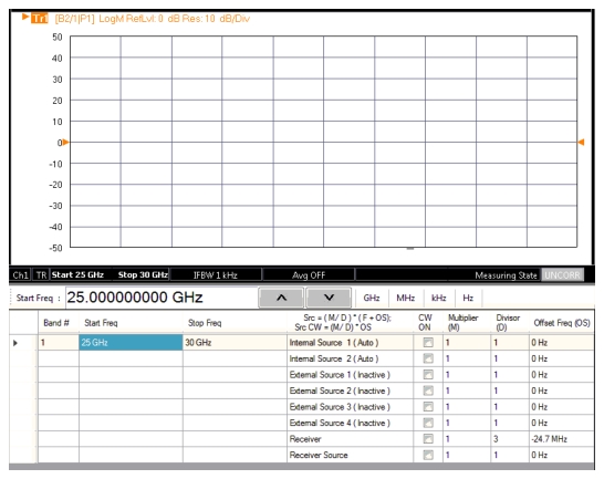
The Receiver equation can be set in this direct IF mode, but because the rear panel IF spigots are being used, the internal receivers are not active. The LO spigots on the front panel are active and the signal present there can be used, but note that the internal LOs are capped at 10 GHz so the receiver equation must be set appropriately. As an example, suppose one wanted to use the internal LO to act as sub-harmonic (1/3) drive for a remote converter and suppose the RF to be converted is at 28 GHz. We wish a 12.35 MHz IF, so the final LO (internal to the remote converter) should be 28.01235 GHz assuming a high-side LO. The sub-harmonic drive should be one-third of that or 9.33745 GHz. The multiple source system adds 12.35 MHz to the equation value so the equation should be reduced by the same amount to compensate. Thus, the receiver equation entry should yield 9.3251 GHz. An example setup is shown in Figure: Multiple Source Harmonic Conversion Example that accomplishes this measurement over a finite range. Note the -24.7 MHz used in the receiver equation. For a simple harmonic conversion using a factor of N, this number will generally be -(N-1)*12.35MHz. If multiple conversions are used or there is a more complex IF plan, the equation will differ. The universal point is that the LO will be programmed to 12.35 MHz above the output value of the equation.
Multiple Source Harmonic Conversion Example
Some of the other selections that are part of the external module control dialog are not particularly relevant to this measurement application. Leveling should be left at RF (leveling within the VNA source chain). Common offset should only be selected if the source(s) and receiver are within about 50 MHz of each other (when multiplication factors are removed)… this is generally not the case. Start delay and VCO overrange can be used (behavior detailed in the previous section) but they are not normally changed for this type of measurement application. The band and receiver checkboxes must, of course, be enabled for the IF switching to happen.