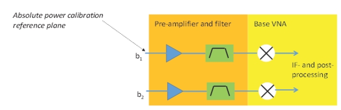
If one can neglect correlation, the measurement is very simple and is a straightforward extension of the 2-port DUT analysis presented earlier in this guide. Two VNA receivers are used along with pre-amplification and filtering, as discussed. A receiver calibration establishes an absolute power reference plane for the cold-source measurements. Note that for non-mmWave measurements (i.e., those made with the base MS464XX VNA and not on one of the ME7838X systems operating in broadband or mmWave mode), the b1 and b2 loops on the VNA proper are used for the noise inputs, EVEN IF A 4-PORT TEST SET IS BEING USED. The instrument can remain in 4-port mode at all times, but the noise connections are not through that test set.
Configuration for Multiple Single-ended or Uncorrelated Noise Measurements
For multiple single-ended or uncorrelated noise measurements, the configuration follows naturally from that for the 2-port DUTs discussed in Noise Figure (Option 41).
The two paths need not be identical but must obey the same rules, as discussed in Noise Figure (Option 41) for overall gain, and should have similar frequency responses in the measurement band of interest. Since correlation is neglected, the differential and common-mode noise power become simply
Equation 20‑9.
The same concepts of receiver offset and network extraction tools discussed in Noise Figure (Option 41) also apply here, except independent files can be loaded for each receiver. In the case of network extraction tools, a single .s4p file can be used where paths can be assigned to each receiver.
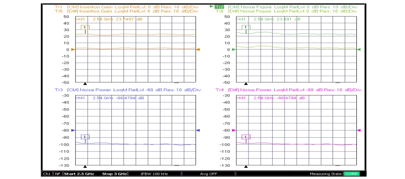
As a basic measurement example, consider a 3-port differential-output amplifier whose noise generators are known to be relatively uncorrelated. The uncorrelated method was chosen and the receiver and noise calibrations performed. As seen in Figure: Three-port DUT with Uncorrelated Differential Output Measurement Example (traces 3 and 4) the common-mode and differential noise powers are the same as is forced by this method. The insertion gains for the two modes (derived from the .s3p file, using Eq. 20‑2, for the DUT that was loaded) differ, however, by more than 20 dB (see traces 1 and 5). As a result, the noise figures (traces 2 and 6) also differ by more than 20 dB. The output of this particular device was well-matched so the use of available gain would not have significantly changed the result.
Three-port DUT with Uncorrelated Differential Output Measurement Example
Although this method forces the differential and common-mode noise powers to be equal, the very different gains for the two modes cause the noise figures to also be quite different.
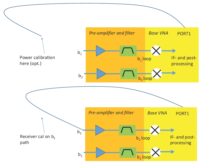
General calibration and measurement procedure:
• Set up composite receivers feeding b1 and b2.
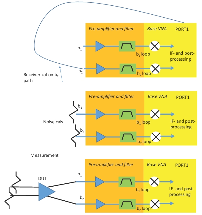
• Perform a power calibration on port 1 (if desired) at a sufficiently low level that the composite receivers will not compress. Perform a receiver calibration (using this power calibration if desired) on both receiver paths. These calibrations can be done while in the noise figure application or can be recalled.
• Perform a noise calibration on both receiver paths with terminations attached to the receiver inputs.