The literature on mixer theory is extensive and many topics will not be covered here. The interested reader is referred to, for example, S. A. Maas, Microwave Mixers, Artech House, 1993 and references therein for a complete treatment.
The central purpose is the translation from one frequency (at the input) to another in an additive (or subtractive) fashion (at the output). As an aside, this chapter and the instrument will generally use the terms ‘input’ and ‘output’ so the names do not have to keep changing depending on the type of conversion. The software will allow labeling of ports as IF and RF (and allow them to be changed) as will be seen later.
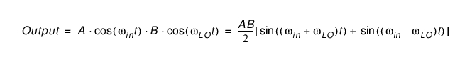
In the simplest sense, the mixer can be viewed as a perfect multiplier so if the input is some sinusoid with frequency ωin and the Local Oscillator (LO) port has some sinusoid with frequency ωLO, then the output signal is given by Eq. 21‑1 below, (ignoring any constant phase terms, it is mainly frequencies we are interested in at the moment).
Equation 21‑1.
Also, the conversion distortions (magnitude and phase) of the mixer itself are not in the above equation. The important point is that sum and difference frequencies are created. Other higher order terms are also created in practice that will be discussed later.
Up Conversion
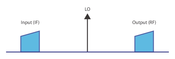
One case is when the sum term is of interest, this is called up conversion and typically the input is labeled as the IF in this case. This is the least complicated case and there is little ambiguity with the signals unless ωLO is very small relative to ωin (not common). The spectra are illustrated in Figure: Up Conversion Signal Spectra.
Up Conversion Signal Spectra
The spectra of signals in an up conversion case are shown here. The LO is normally greater than the input but this is not a requirement.
Down Conversion
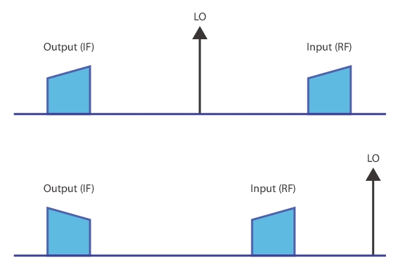
The difference frequency case (down conversion) can be more complicated in that now the relationship of the input frequency range to the LO makes a difference in the behavior (due to a sign flip in Eq. 21‑1). If the input frequency range is greater than the LO (Figure: Down Conversion Signal Spectra), then there is no inversion. If the LO is greater than the input, there is an inversion. One could argue that the signs in Eq. 21‑1 could be re-arranged arbitrarily, but the key point is if there is a minus sign before the input frequency. If there is, then the output sweep will be in an inverse direction from the input sweep and there is a phase conjugation.
Various terms are used to separate these two cases including ‘high-side LO vs. low-side LO’ and ‘USB vs. LSB conversion’ (for upper sideband vs. lower sideband). This document and the instrument software will generally use the latter terminology.
Down Conversion Signal Spectra
The spectra of signals in down conversion cases are shown here. The LO position relative to the input affects the behavior. The spectra picture on top is of a low-side LO or USB case while the spectra picture on the bottom is of a high-side LO or LSB case.
One may ask about the negative frequency implications in Eq. 21‑1 of the LSB case but the sign simply flows out of the sinusoid and inverts the phase. As far as the instrument is concerned, it takes the absolute value of the computed frequency before programming the hardware, which is just what the equation is telling it to do.
Up to this point, we have been treating the conversion as ideal. In practice, the mixer (or converter) will have gain/loss and some phase shift (both typically frequency dependent), some mismatch, and potentially considerable non-linearity. The real embodiment of Eq. 21‑1 is more like that shown in Eq. 21‑2 below:
Equation 21‑2.
There are also additional higher order terms. This means that any integer combination of input and LO frequencies can appear at the output (and many do). These other frequency components are often termed spurs with a nomenclature like an ‘M by N spur’ if the output frequency is of the form M ωin ± N ωin. The measurement of these spurs is also possible with the MS464xB and will be discussed towards the end of this chapter.
As might be suggested by Eq. 21‑2, one could conceivably use a harmonic of the LO to do the heavy lifting of conversion. That is, one could intentionally use the 1 by N ‘spur’ for the conversion. This is indeed done, particularly for higher frequency and millimeter wave applications where creating a sufficiently low noise fundamental LO is either too difficult or too expensive. Harmonic mixers and samplers (or subharmonic mixers which is confusing but equivalent terminology usually) are handled by the multiple source control system described in another chapter.
Another terminology problem is that of mixers vs. converters vs. frequency conversion devices. There is some lack of consistency in the industry but often a converter is a mixer with some additional functionality (gain blocks, switching, etc.). A frequency conversion device can be a mixer but is also sometimes use to denote a multiplier. This chapter is concerned with those devices that translate frequency in an additive or subtractive fashion but with additional gain or linear networks allowed. We will thus use the terms mixer and converter somewhat interchangeably. Multipliers are also covered by the very general multiple source control section in another chapter.