The guided setup and wizard sections of the application menu are split into two parts: one that only sets up the active channel and acts more as a guide (will be discussed now) and a multi-channel wizard that helps one configure multiple measurements in a more organized fashion (to be discussed later in this chapter). Details on the controls themselves are covered in the operations and user interface manuals. The purpose here is to discuss how the controls relate to the mixer measurement concepts discussed previously.
Mixer Setup Dialogs
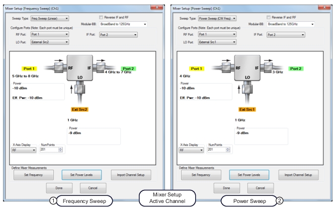
The basic setup screens for this active channel method are shown in Figure: Mixer Setup Dialogs. The IF and RF ports can be assigned to different VNA physical ports as has been discussed and the IF/RF labeling can be swapped (see the check box near the top). Both frequency sweeps (of input and LO possibly) and power sweeps are supported and are chosen from a pull-down menu. Also part of the input/output duality is how the x-axis of the plots are labeled and this is handled by the pull-down in the lower left part of the dialog. In the case of a fixed output frequency or a fixed input frequency, labeling the x-axis with the fixed variable is usually not helpful.
Mixer Setup Dialogs
1. On left, MIXER SETUP (FREQUENCY SWEEP).
2. On right, MIXER SETUP (POWER SWEEP).
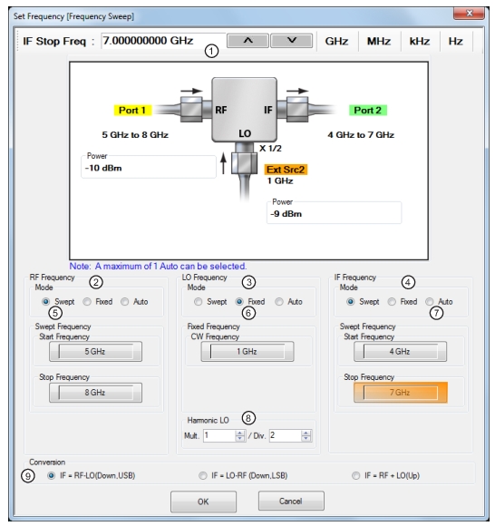
The frequency ranges (including the possibility of reverse sweeps) are shown in the dialog and are set up using a sub-dialog as shown in Figure: Frequency Setup Dialog for Frequency-Sweep Case. The conversion direction and sideband choices discussed previously are handled here and there are many permutations possible. The conversion direction is selected from the radio buttons at the bottom and note the two downconversion selections discussed previously (USB and LSB). Input, output, or LO may be fixed (generally only one of them) and an Auto selection may be used to let the system calculate the frequencies for one of the ports. It is, of course, possible for an invalid frequency combination to be entered (out of range of the hardware) but this will be scanned for when the OK button is selected.
The dominant frequency variable (normally RF but will be IF if the Reverse IF and RF checkbox is selected) must have a start frequency less than the stop frequency when in a swept condition.
Frequency Setup Dialog for Frequency-Sweep Case
1. Frequency input field toolbar. The label changes depending whether RF, IF, or LO are selected.
2. RF Frequency mode and value area.
3. LO Frequency mode and value area.
4. IF Frequency mode and value area.
5. Mode set as Swept. Any combination of the RF, IF, and LO ports can be set as Swept. When selected, Start and Stop Frequency fields appear.
6. Mode set as Fixed. Any combination of the RF, IF, and LO ports can be set as Fixed. When selected, a CW Frequency field appears.
7. Only one port can be set as Auto. If selected, the instrument determines the frequency settings based on the other two values and the Conversion selection.
8. The Harmonic LO entry allows one to describe any frequency multiplication and/or division that may be present between the synthesizer providing the LO signal and the DUT's fundamental frequency converter. This entry can also be used when the DUT is a harmonic mixer or sampler that has implicit frequency multiplication in the LO path.
Note: A label showing the Harmonic LO ratio is displayed at the mixer schematic LO port when multiplier/divisor (M/N) ratio is not equal to 1.
9. Conversion setting. Changes based on whether RF is input or output.
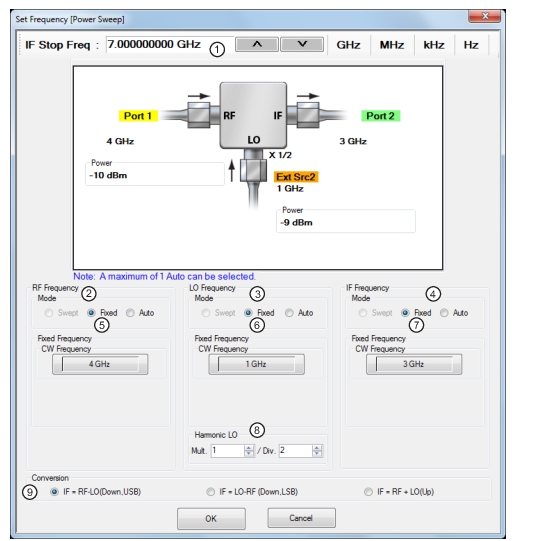
In the case of a power sweep, all of the frequencies must be CW so the frequency selection dialog simplifies as shown in Figure: Frequency Setup Dialog for Power Sweep Case. The same sideband and conversion choices apply; there is just no frequency sweeping involved in this measurement setup.
Frequency Setup Dialog for Power Sweep Case
1. Frequency input field toolbar. The label changes depending whether RF, IF, or LO are selected.
2. RF Frequency mode and value area.
3. LO Frequency mode and value area.
4. IF Frequency mode and value area.
5. RF Mode setting can only be Fixed or Auto. Only one mixer port can be Auto. If fixed, RF CW frequency is input in field below.
6. LO Mode setting can only be Fixed or Auto. Only one mixer port can be Auto. LO CW frequency is input in field below.
7. IF Mode setting can only be Fixed or Auto. Only one mixer port can be Auto. IF CW frequency is input in field below.
8. The Harmonic LO entry allows one to describe any frequency multiplication and/or division that may be present between the synthesizer providing the LO signal and the DUT's fundamental frequency converter. This entry can also be used when the DUT is a harmonic mixer or sampler that has implicit frequency multiplication in the LO path.
Note: A label showing the Harmonic LO ratio is displayed at the mixer schematic LO port when multiplier/divisor (M/N) ratio is not equal to 1.
9. Conversion setting. Changes based on whether RF is input or output. If RF is input, equations show conversion calculations for IF. If IF is input, equations show conversion calculations for RF.
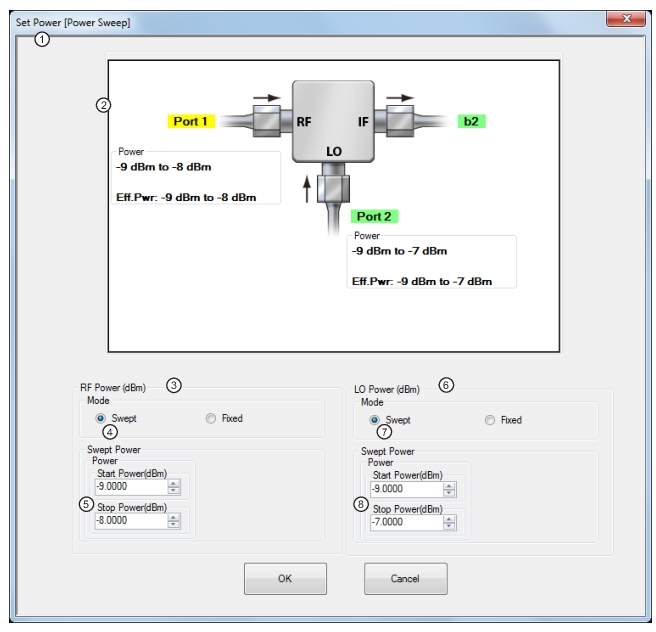
Correspondingly, the power setup is now more detailed as suggested by Figure: Power Setup Dialog for the Power Sweep Case. There are no conversion complications, but there could be simultaneous sweeping of power on input and LO (not commonly done, but possible). The swept power input is often done to look at gain compression of the DUT, while LO power sweeps are often employed to look at the saturability of the LO path. The latter can be important since it has many linearity implications depending on the DUT technology.
Power Setup Dialog for the Power Sweep Case
1. SET POWERS (POWER SWEEP) Wizard Dialog Box
2. Mixer Schematic—Port assignments and power levels are updated automatically.
3. RF Power (dBm) controls.
4. RF Power Mode set as Swept with option of Fixed.
5. Swept start and stop power input fields. The input field is CW Power when Fixed Power Mode is selected.
Modifications to Pull-downs when Option 31 and One of 051/061/062 are Available
The modifications to the pull-downs when Option 31 and one of 051/061/062 are available are illustrated here. This allows the second source to be used as the LO in the mixer measurement.
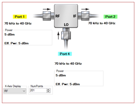
An example mixer setup on a 4-port system is shown in Figure: (4-Port) Mixer Setup. The Input (RF) and LO are driven from the two internal sources (not all port combinations are permitted).
(4-Port) Mixer Setup
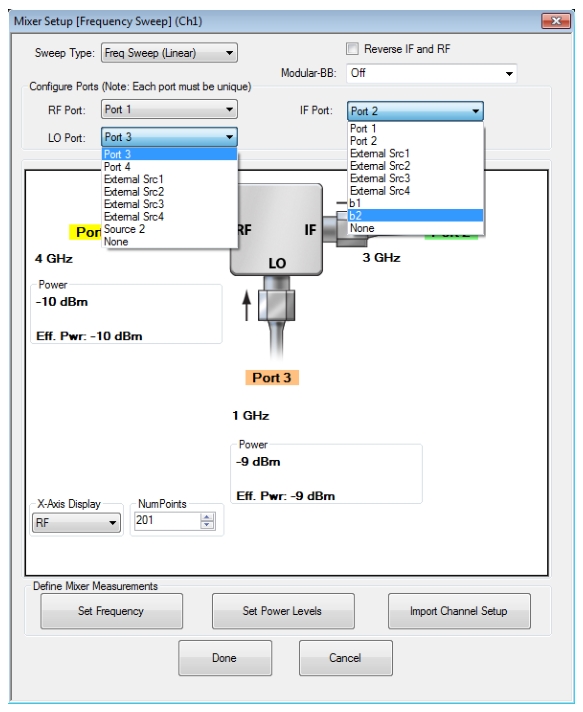
Most of the concepts discussed above map over to 4-port systems. In the single-source case, the only change is the ability to use any two ports as the input and output (or an LO can be assigned to one and an external synthesizer used for the input). For dual source 4-port systems, there is some additional flexibility in that the two ports can be used for input and LO and an additional port can be used for the output. The only constraint is that the input and LO must be able to access the two sources so allowed port pairings are 1-3, 1-4, 2-3, and 2-4. All mixer calibrations are available. An example setup of this type is shown in Figure: (4-Port) Input as Port 1, Output as Port 2 and LO as Port 3.
As always, external sources can be used for input and LO (with calibration restrictions if used as the input). b1 and b2 can be used for the receiver in the dual source case. Note that these entries still refer to the loop access points on the base VNA (so there are only two).
(4-Port) Input as Port 1, Output as Port 2 and LO as Port 3
Example Mixer Setups
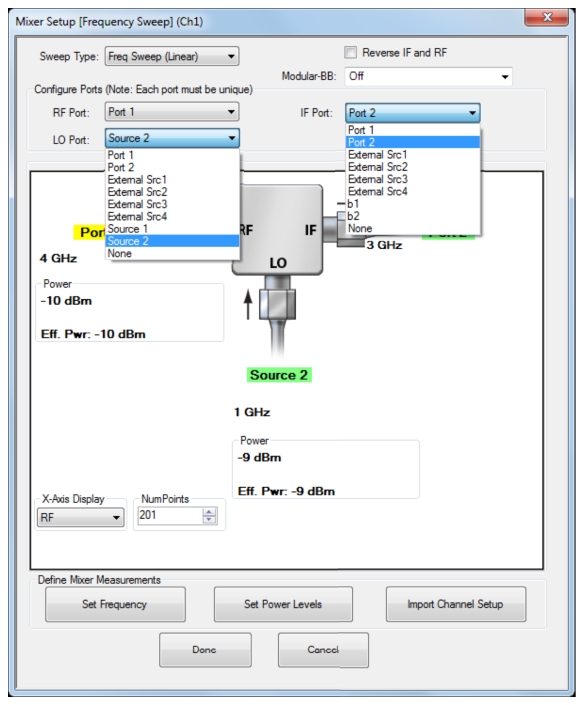
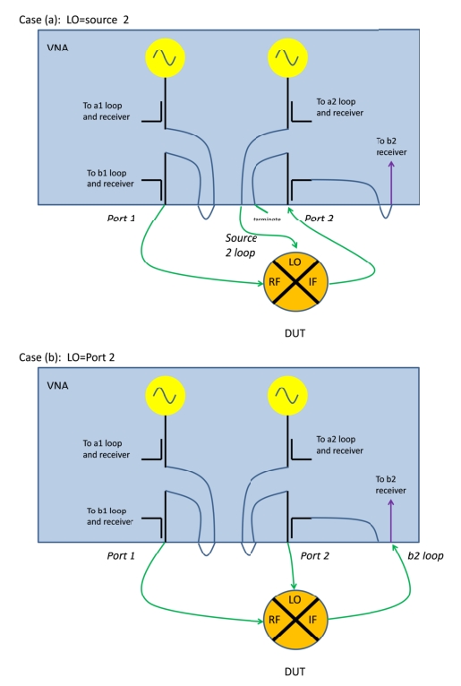
One can, for example, select source 2 for the LO and then port 2 for the IF or port 2 for the LO and b2 for the IF. These choices all make use of the independent sources available on ports 1 and 2 and the ability to work around the ports to separate LO and IF signals (in this case). To see how these configurations might be arranged, consider the two setups outlined in Figure: Setups for Source 2 and Port 2 LO Drive.
Setups for Source 2 and Port 2 LO Drive
• Case (a): LO = Source 2
In this case, the source loop is used to access the LO drive and the mixer IF can feed the port 2 coupler as usual (one could also select b2 and feed the IF directly into the receiver for more dynamic range). Since the leveling circuitry is behind the source loop, full power control and power calibrations will still be available for the LO. The LO is available from the loop port marked with the tail of the arrow as shown in the figure. It is recommended that the unused loop port (marked with the head of the arrow) be terminated to help improve the raw match that the DUT output will see looking into port 2.
• Case (b): LO = Port 2
In this case, the LO is fed from the port connector and the IF can be connected directly to the b2 receiver (b2 loop connector marked with the head of the arrow). The noise floor is lower when using the loop receiver access (by about 13 dB) but the compression point is as well (by the same amount) so padding may be necessary for DUTs with output power ~> –3 dBm to avoid system receiver compression. The unused loop port can also be terminated in this case but it is less critical here since it leads to only a coupler arm (isolated from the signal path).
In both of these examples, port 1, source 1 and b1 can be substituted into the discussion if the RF is driven by port 2. Also, all of the terms swap if the Reverse IF and RF checkbox has been checked. Note that if the second source is used as the LO, the enhanced match calibrations will not be available since that calibration relies on full reversing measurements which are not possible if one source is dedicated to the LO drive. When doing a normalization calibration, the relevant connection for the 'thru' step on the output side would be the port 2 connector or the b2 loop connector (head of the arrow) as one might expect.
Note
An additional point for all active channel mixer setups is that the input port frequency range must have a start frequency less than the stop frequency. The output and LO ports are allowed to sweep backwards.
Mixer Power Cal Assistant
At the conclusion of the Active Channel setup (hitting ‘Done’ and the configuration has been validated), the user will be offered a directed path to a user power calibration process. Such a power calibration is recommended for increased accuracy (particularly at millimeter wave frequencies) and the directed path helps by setting up all of the power calibration variables based on the mixer setup for power calibration at both RF and IF frequencies. An appropriate power meter must still be connected to the system (GPIB or USB) and to the relevant port. If the user skips this directed path, a power calibration can always be orchestrated manually at a later time.