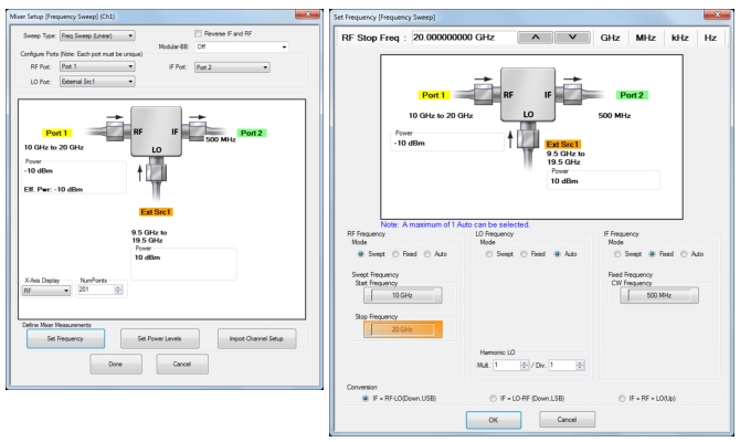
Consider that one wishes to make a conversion loss measurement of a DUT with a 10 to 20 GHz input range, a fixed 0.5 GHz output and a low-side LO. External synthesizer 1 will be used as the LO (and it is on the GPIB address of 4, which is default for external synth 1) and it has been connected to the GPIB and the 10 MHz reference out of the VNA and turned on. The LO power is to be +10 dBm and the input power is to be -10 dBm. The setup dialogs for this scenario are shown in
Figure: Example Setup for 10 to 20 GHz Downconverter. Here we used the ‘auto’ function on the LO entry to simplify things. Note the selection of the conversion direction on the frequency setup. Once the
Done button is selected on the main dialog, the setup will be verified and the system placed into a converting mode where the source at Port 1 is sweeping over 10 to 20 GHz and the receiver is fixed at 0.5 GHz.
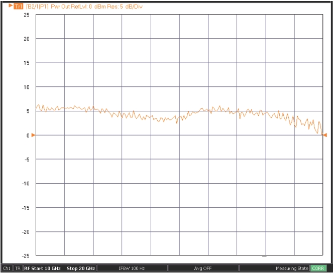
The next step would normally be to go to the calibration menu and select either a normalization or an enhanced match calibration for this conversion loss measurement. During the normalization calibration, only a thru line connection is needed as discussed earlier. The measurement result for this case is shown in
Figure: Example Conversion Gain Measurement with Normalization-Based Calibration. No port padding was used and the DUT was not particularly well-matched so there is some ripple.
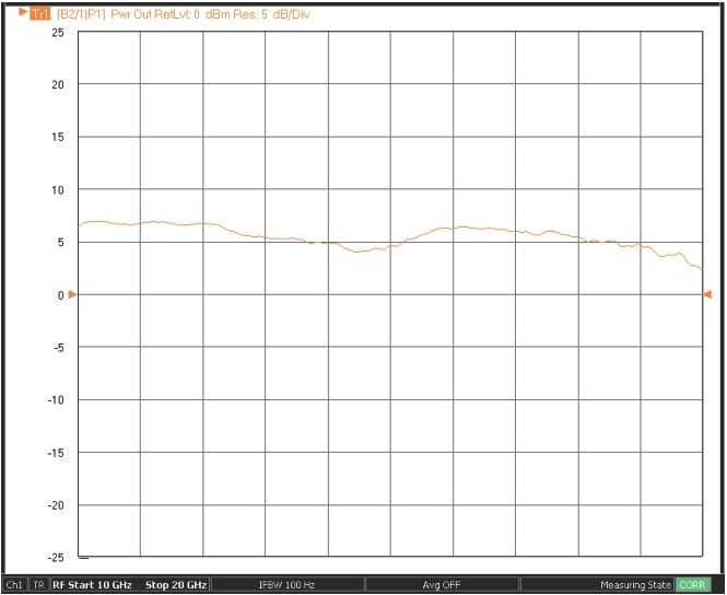
An enhanced-match calibration was also performed on this setup and the measurement results are shown in
Figure: Example Conversion Gain Measurement with Enhanced Match Calibration. A standard manual OSL calibration kit in the K connector (3652X) was used for the reflectometer calibration steps. The measurements were not identical due to some bias changes on the DUT but the reduction in ripple is apparent.