Procedure for a Typical Multiple Channel Mixer Measurement
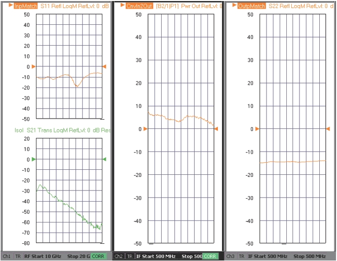
We will extend the example of Section 18-8 now to include additional measurements. The setup parameters are the same as before except now we will request input match, output match, forward conversion loss, and input-to-output isolation. The measurement results are shown in Figure: Three Channel Measurement Results.
• Channel 1:
Sweeping both source and receiver 10 to 20 GHz to measure input match and input-to-output isolation
• Channel 2:
Sweeping the source 10-20 GHz with the receiver fixed at 0.5 GHz to measure conversion loss (actually more is going on here since an enhanced match calibration was used so this channel also measures DUT input and output match behind-the-scenes).
• Channel 3:
CW measurement at 0.5 GHz to get the output match. Note that although the source and receiver are CW during this measurement, the LO is sweeping so one does see a variation over the sweep. Since the LO sweep range is known to be 9.5 to 19.5 GHz (or one can plot with this x-axis), the correlation can be studied.
Three Channel Measurement Results
The three channels of measurement results for our example are shown here.