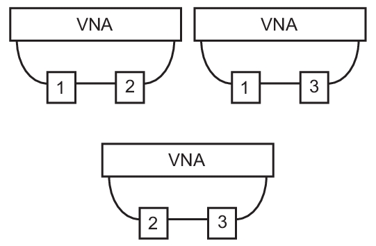
This section provides a brief overview of the NxN method and how the application within the MS464xB Series VNA is used. The idea is that there are three devices that should or must be measured in pairs, and to measure every pair-wise combination of them. This collection of measurements provides enough information to extract the transmission characteristics of each of the devices. The information on any one of the first three devices can then be used to de-embed from measurements when this reference device is paired with any number of other parts. The measurements pairings to get started are shown in Figure: NxN Technique Measurements. Device 2 is required to be reciprocal.
NxN Technique Measurements
If the devices are non-translating, few precautions are needed. If the loss of the devices gets high relative to the dynamic range of the VNA (in whatever state it is being used), then accuracy will be degraded. Normally a full 2-Port calibration is performed on the VNA (so that outbound matches can be corrected) but simple normalization calibrations can be adequate. Note that the inner matches cannot be corrected (since no access is available) hence match is not an extracted parameter. Full s2p files will be generated for the devices but S11 and S22 will be set to zero.
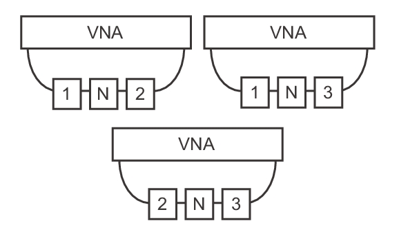
If the devices are poorly matched, it may be necessary to place a pad or other network between the devices. As long as this inner network is present for all measurements and its S-parameters are known, its effects can be removed. This technique was originally used in mixer measurements, hence it is termed an IF network. This measurement setup is shown in Figure: NxN Measurement Setup (using an inner network N). The three measurements required to execute NxN are shown here when using an inner network N (which may be a pad or filter combination). Device 2 is required to be reciprocal.
NxN Measurement Setup (using an inner network N)
NxN is a popular mixer technique since the VNA sees the same input and output frequencies. Thus normal calibrations can be used, no frequency offsets are needed and there are no reference complications. The first device in each pair will be used as an up converter or down converter and the second device will be the opposite. Device 2 must be able to fulfill both roles so it must be a passive mixer. The same frequency plan must be used in all of the measurements.
Typically a common LO is used for all devices (with some splitter assembly) but multiple LOs can also be used as long as they share a common 10 MHz reference. These sources can often be controlled using multiple source control (see separate section in this Measurement Guide for more information). If one of the devices has multiple conversion stages, it may be desirable for the other devices to have the same conversion pattern for optimal trace noise. If this is not feasible, the only real requirement is that the input and output frequencies for all devices match.
The nature of the frequency plan between the devices must be known if the IF network (N in Figure: NxN Measurement Setup (using an inner network N)) is to be removed. If the first device is not performing an inversion (i.e., if the input signal ramps up in frequency, the output signal ramps up in frequency) then the lookup of the IF network behavior is not inverted. If the first device does perform an inversion, then the lookup of the IF network must be inverted.