In earlier chapters, a considerable amount of detail on various calibration algorithms and calibration types has been covered. The 3- and 4-Port variants of these calibrations are different from their 2-Port relations in fairly straightforward ways. The purpose of this subsection is to show where the differences are and how these calibrations can be properly configured.
A logical starting point is to ask what is different between measuring, say S41, using a 4-Port calibration versus measuring it with a 2-Port calibration while properly terminating Ports 2 and 3. The quick answer is nothing, assuming the terminations are of good quality and one does not care about measurement time when measuring many parameters (while one swaps terminations around to get all of the S-parameters). If one just connected Ports 2 and 3 of the DUT to VNA ports, the results would probably not be as good since the raw broadband return loss of a VNA port is usually not better than 15 dB. To illustrate this concept, consider the measurement of isolation of a 4-Port coupler (S41 in the previous discussion). If a full 4-port calibration is performed, the dotted line in Figure: Measurement Improvement for Full 4-Port Calibration is obtained. If instead only a 2-Port cal is performed and the other coupler ports are left terminated in the test set (seeing the raw match of those ports), then the solid line of Figure: Measurement Improvement for Full 4-Port Calibration is obtained. The error here could be on the order of 10 dB at the –30 dB level.
Measurement Improvement for Full 4-Port Calibration
An example showing the measurement improvement of a full 4-port calibration over a partially terminated 2-port calibration is shown here.
By performing a full 3- or 4-Port calibration, the effective return loss of those other ports is improved to that of the residual load match (typically 30-50 dB depending on the calibration algorithm and components used) thus improving the measurement result. Thus overall measurement time and accuracy are the usual drivers for considering 3- and 4-Port calibrations.
The first step in understanding these calibrations is to look at the complete error model for N ports. As is apparent from the figure below (Figure: N-Port Error Model), it is a straightforward extension of the 2-Port error model covered in Calibration and Measurement Overview. The directivity and match terms are basically functions of the port itself so one must just add these terms for the additional ports.
Tracking
Tracking is again broken down into reflection tracking (the frequency response on a reflection measurement) and transmission tracking (the frequency response on a transmission measurement). Reflection tracking then also is a port property and can be assigned for each additional port. Transmission tracking is a property of a pair of ports (the correction to get a through line to measure Sij=1 after other port errors have been handled) hence this term must be assigned for every permutation of two ports.
Isolation
Finally isolation is usually also considered the property of a pair of ports so the same permutation will be required. The last statement is not entirely valid if isolation is dependent on DUT impedances and is normally reserved to correct for isolation deep in the instrument. This distinction will be ignored for now since the isolation step is optional.
New Error Model
Thus we have a fairly straightforward new error model as shown below (Figure: N-Port Error Model). As before, the pair of lines (in the diagram) per port is to help delineate incident and reflected waves. The reflection tracking for port q can be thought of as the product of taq and tbq; the transmission tracking from port k to port l can be thought of as the product of tak and tbl (no new information is being added, it is just being redistributed).
N-Port Error Model
An N-Port error model is shown here. Directivity, match and reflection tracking can be assigned on a per-port basis while transmission tracking can be assigned on a pair-of-ports basis. Isolation is also nominally assigned on a pair-of-ports basis but that does have problems (isolation is often ignored practically).
Menus
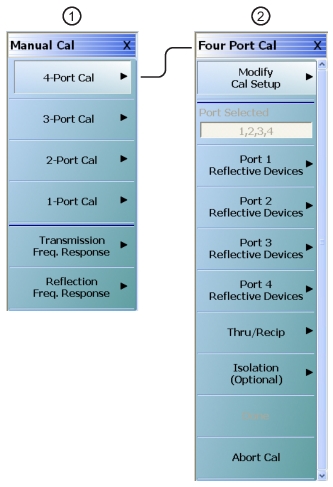
As might be expected, the main calibration menu will have a selection based on the type of calibration (full or nearly so versus frequency-response) and the number of ports. The MANUAL CAL menu below (at #1 left in Figure: MANUAL CAL (MANUAL CALIBRATION) and FOUR PORT CAL Menus) provides the selection path to the FOUR-PORT CAL menu (at #2 below). This menu is the calibration execution menu for a 4-Port calibration (defined standards call.
MANUAL CAL (MANUAL CALIBRATION) and FOUR PORT CAL Menus
1. The MANUAL CAL menu (at left) provides access to all multiport calibration modes. The 4-Port Cal button provides access to the FOUR PORT CAL procedure menu for a 4-Port VNA.
2. The FOUR PORT CAL calibration execution menu (at right) for a 4-Port calibration (defined-standards calibration).
The menus for the lower port count defined-standards calibrations follow in a predictable fashion. On the FOUR PORT CAL menu (at 2 right in Figure: MANUAL CAL (MANUAL CALIBRATION) and FOUR PORT CAL Menus above), the second field from the top, a read-only box, will indicate which ports are in play for the current calibration. The details on selecting these ports will be presented later.
Transmission Tracking
The key complication of multiport calibrations lies in the handling of transmission tracking. Since the reflection and transmission tracking terms overlap, they are not entirely independent. The following is the relationship that one can pull directly off of Figure: N-Port Error Model:
Equation 24‑12.
In reality, this must be modified slightly for load match/source match changes, but the redundancy concept still applies. To see how this is used, consider the redundant through line problem (as in previous chapters, we will use the term “through” to denote any fully defined transmission line whether it be of zero length or not). Suppose we have connected throughs between Ports 1-2, 1-3, and 1-4 sequentially. Presumably, the first three term types (directivity, source match, and reflection tracking) have been computed for all four ports. The through connects allow us to compute all of the load match terms and all transmission tracking terms except for et32, et23, et24, et42, et34 and et43. These last tracking terms can be found with the following forms of Eq. 24‑12 (above) shown below in Eq. 24‑13:
Equation 24‑13.
Again, the above is modified slightly because of match differences. This process is termed the use of redundancy since the reflect measurements and the through measurements do overlap to a certain degree. Thus, one does not need to connect all six (6) possible through lines in a 4-Port calibration or all three (3) possible through lines in a 3-Port calibration. The basic requirement is that all ports be “connected” in some way with a line. Now, additional throughs can always be used and can improve accuracy of the tracking terms by a certain amount. There are many cases, however, where it is difficult to construct a high quality line between ports (orthogonally positioned wafer process for example) and the use of redundancy will produce a better result than trying to use a poor through during the calibration. Similar analyses are used for all calibration types so that the user will see considerable flexibility in how the throughs/lines are defined.
Load Match
A related topic is load match (primarily for defined-standards calibrations) since it can generally be computed in multiple different ways since multiple throughs are involved. The guiding principle is the first-in rule: the first through measured will be used to compute the load match for the ports involved, the second through will be used for its ports but it will not overwrite earlier computed load matches, and so on. This allows the user to optimize load match performance by measuring the highest quality throughs first.
A consistent load match is guaranteed by generally using the test set terminations to form the reference load for all transmission measurements. When the linkage to the VNA termination is required (for reciprocal calibrations and for the LRL/LRM families), the final load matches are transformed to the test set termination in order to guarantee consistency. This concept is shown below (Figure: Load Match Plane Translation). Thus whenever a transmission parameter is measured, a unique load match is always defined and the corrections are self-consistent.
Load Match Plane Translation
The concept of load match plane translation is shown here. Although the connection (shown on the left) may be needed for LRL/LRM and SOLR-like calibrations, the reference plane for load match will always be translated to the test set termination (as shown on the right).
Setting Up the Defined Standards Calibration
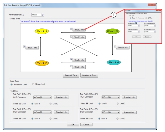
The next topic is that of setting up the defined standards calibration. Consider the dialog shown below (Figure: FULL FOUR PORT CAL SETUP Dialog Box—SOLT/R—Coaxial) that is used for setting up a 4-Port calibration using the SOLT/R algorithm.
FULL FOUR PORT CAL SETUP Dialog Box—SOLT/R—Coaxial
1. Selecting button opens Thru Info Dialog where the user can alter Thru, Reciprocal or S2P Thru parameters. See Figure: THRU INFO Dialog Box for details.
Selecting Possible Throughs
As might be expected, there are the usual items for selecting the port connector types, the type of load (broadband or sliding) and the reference impedance. What is somewhat different is the through selection tableau. The six possible throughs are shown, each having a button allowing the definition of that line as shown below (Figure: THRU INFO Dialog Box). As discussed earlier, at least three throughs must be selected such that all ports are “connected.”
• Allowed:
• 1-2, 1-3, and 1-4
• 1-3, 2-4, and 1-4
• Etc.
• Not allowed (without adding more lines):
• 1-2, 1-3, and 2-3 (port 4 is not “connected”)
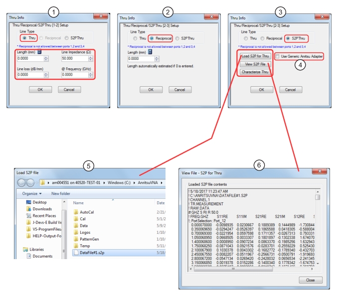
THRU INFO Dialog Box
Typical through line configuration in the THRU INFO dialog box for the defined-standards calibrations.
1. Thru Info Dialog—Line Type Thru selected, allowing configuration of Thru
2. Thru Info Dialog—Line Type Reciprocal selected, allowing configuration of Thru
3. Thru Info Dialog—Line Type S2P Thru selected, allowing loading, viewing and generation of S2P files
4. Use Generic Anritsu Adapter (check box)—Checking this box will automatically load a default .s2p file for a generic Anritsu adapter. Note that selecting the checkbox disables the Load S2P for Thru and Characterize Thru buttons.
5. File Load Dialog
6. View S2P File contents window
As suggested by the figure above (Figure: THRU INFO Dialog Box), each of the selections may be defined as a “through” or as a “reciprocal” as discussed in earlier chapters. From the point-of-view of “connectedness”, these designations are equivalent. As discussed in an earlier chapter, however, there is some accuracy degradation (particularly with regard to load match) that can be compounded if all lines are reciprocals. This point is discussed in more detail in the uncertainty section.
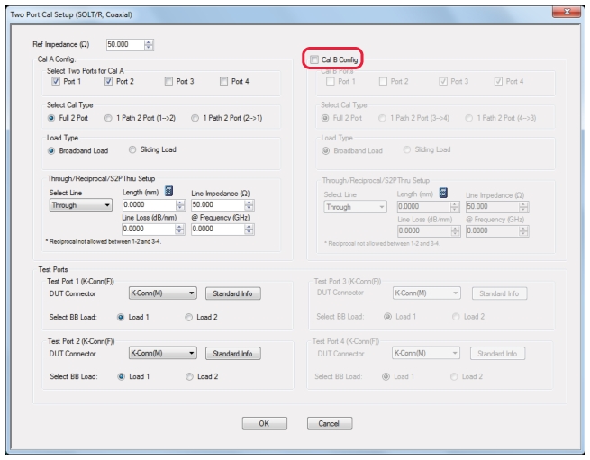
The three port calibration is analogous and the menus are covered in the operation guide. One port (to include reflection response calibrations) and 2-port calibrations are a little different in that multiple calibrations are allowed. Since it is a 4-port instrument, the user is allowed to perform two 2-Port calibrations or up to four 1-Port calibrations simultaneously. The 2-port calibration setup dialog is shown below (Figure: TWO PORT CAL SETUP (SOLT/R, COAXIAL) Dialog Box) to illustrate the option of another calibration (Cal B in this dialog).
TWO PORT CAL SETUP (SOLT/R, COAXIAL) Dialog Box
Typical calibration setup for a 2-Port calibration with selections of SOLT/R, Coaxial, and Cal B Not Selected. The 2-port modify setup (SOLT/R) dialog is shown here to illustrate the multiple calibration functionality.
If Cal B is activated from the check box, then the other two ports (not defined under Cal A) can be used to form an independent calibration. Port overlap is not allowed in order to avoid error-term self-consistency issues.
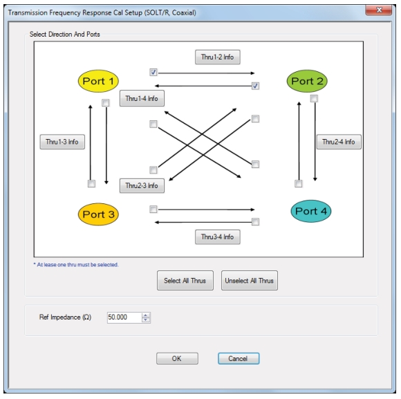
Transmission frequency response calibrations generalize as one might expect since there are now 12 transmission S-parameters potentially available to normalize. The dialog is shown below (Figure: TRANSMISSION FREQUENCY RESPONSE CAL SETUP Dialog Box—SOLT/R—Coaxial). As with the full calibrations, the throughs may be defined independently although the reciprocal choice is not available in this case. Note that unlike through selections in the full calibrations, the directions can be independently selected in this case. As is the case with 2-port systems, it is allowed to normalize, say, S21 but not S12. In the full calibration case, both directions are always required.
TRANSMISSION FREQUENCY RESPONSE CAL SETUP Dialog Box—SOLT/R—Coaxial
The transmission frequency response modify setup dialog is shown here for a 4-Port system.
The above dialogs and setup requirements are completely analogous for SSLT/R and SSST/R algorithms. The LRL/LRM family, however, is somewhat different.
LRL/LRM Calibrations
In this implementation LRL/LRM family, there is a basic structure that is fundamentally 2-Port like in nature. As such, the 4-Port LRL/LRM calibration will be defined as a pair of basic 2-Port calibrations linked together by one or more through measurements (to complete the path linkage as for defined-standards calibrations). This can have an additional benefit in certain cases since it allows the hybridization of reciprocal and defined-through approaches (on the additional paths) with LRL/LRM approaches on the base paths.
A situation where this is useful is shown in the figure below (Figure: On-Wafer Line Path Quality) where orthogonal on-wafer probes are being used. It is relatively easier to define good transmission lines on the horizontal and vertical paths (1-3 and 2-4) but less so, at least for higher frequencies, on the other paths (bends in the required lines causing radiation or otherwise leading to reflections). Such a problem is a good candidate for hybridization.
On-Wafer Line Path Quality
An on-wafer configuration where some line paths are more likely to be of higher quality than others. The solid lines will generally not be an issue but a transmission path illustrated by the dotted line (S-W) may be electromagnetically compromised at higher frequencies.
4-Port LRL/LRM Calibrations
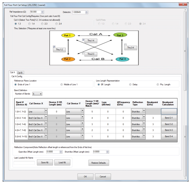
The configuration dialog for 4-Port LRL/LRM calibrations is shown in the figure below (Figure: FOUR PORT CAL SETUP (LRL/LRM, COAXIAL) Dialog Box). Note how the primary LRL/LRM ports are defined and how additional information may be required for the continuation lines. The two 2-Port calibrations are defined on the two tabs labeled Cal A and Cal B. Each tab alone looks the same as the 2-port LRL/LRM calibrations discussed in earlier chapters. Note that on the actual display all of the information may not be visible and a scroll bar may be required.
FOUR PORT CAL SETUP (LRL/LRM, COAXIAL) Dialog Box
The modify calibration dialog for 4-Port LRL/LRM calibrations is shown here.
As in the 2-port case, up to five bands may be defined with various permutations of lines and matches. Also as in the 2-port case, the transition frequencies between each of the bands are adjustable to maximize convenience and calibration accuracy. For more details on these choices, see LRL/LRM Calibration of this guide. The Cal A and Cal B band definitions do not need to be the same and, indeed, they can actually have no calibration devices in common. Such a situation may arise in a mixed media configuration but it does place some constraints on the completion thru definitions.
Three Port LRL/LRM Calibration
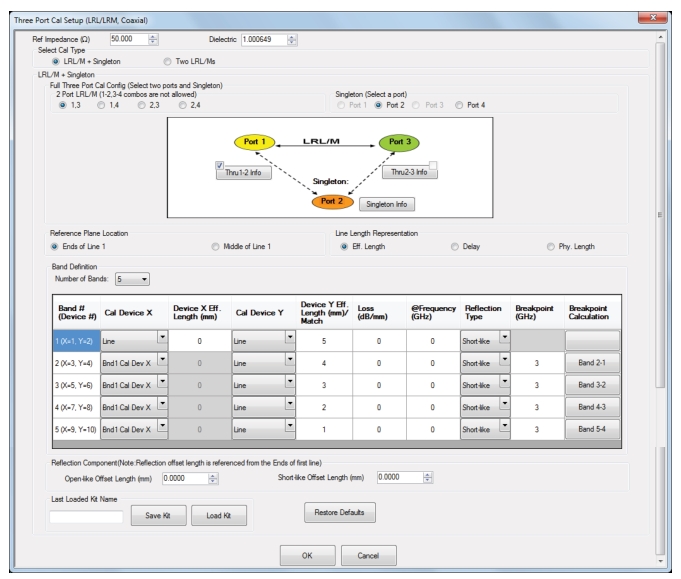
Much like the 4-Port LRL/LRM calibration, the 3-Port version is constructed from a pair of 2-Port LRL/LRM calibrations (unlike the defined-standards approaches). Obviously there is going to be port overlap. The first calibration will define the port reflectometer parameters on the overlap port. The modify calibration dialog for this situation is shown below (Figure: THREE PORT CALSETUP (LRL/LRM, COAXIAL) Dialog Box—Two LRL/Ms—Cal A Tab).
THREE PORT CALSETUP (LRL/LRM, COAXIAL) Dialog Box—Two LRL/Ms—Cal A Tab
The modify calibration dialog for the three port LRL/LRM calibration is shown here.
The 2-Port calibration situation for LRL/LRM is similar to that shown for the defined-standards case: it is allowed to perform two of these calibrations in parallel. Aside from the additional definition required, the approach is the same as discussed in an earlier chapter.
This 3-Port calibration can also be constructed from a single 2-Port LRL/LRM cal together with a singleton definition. This version is shown below (Figure: THREE PORT CALSETUP (LRL/LRM, COAXIAL) Dialog Box—LRL/M + Singleton). The single LRL/LRM cal must be defined as usual and the one or two extra thrus must also be defined as before.
THREE PORT CALSETUP (LRL/LRM, COAXIAL) Dialog Box—LRL/M + Singleton
In addition, a single defined standard must be measured at the singleton port defined under the Singleton Info button as shown below (Figure: SINGLETON REFLECT Dialog Box). The standard is allowed to be an open or a short and the usual offset plus inductance or capacitance polynomials are supported. The measurement of this additional standard allows one to distinguish between load match and source match at the singleton port. Note that in this case, the connections to the singleton port must be thrus (reciprocals are not allowed). The interconnect is used to derive the singleton ports reflectometer behavior so that additional restriction is required.
SINGLETON REFLECT Dialog Box
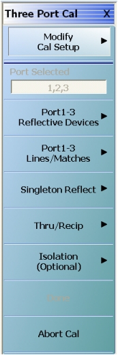
The calibration steps are a bit different for this type of calibration and the step menu is shown below (Figure: THREE PORT CAL Menu—LRL/LRM—Coax—One LRL/M + Singleton). The extra singleton button reflects the asymmetric nature of the information required from this port.
THREE PORT CAL Menu—LRL/LRM—Coax—One LRL/M + Singleton
As with the 2-port LRL/LRM case, the three port calibrations can have up to five bands using various combinations of lines and matches to cover the desired frequency range. In the case of Two LRL/Ms, the two sub-calibrations do not need to use the same band definitions nor the same calibration devices. For more details on band and device selection, see LRL/LRM Calibration of this guide.
The multiline TRL calibrations (mTRL; covered in more detail in mTRL Calibration) also have logical extensions to four port cases. Just as with the regular LRL/LRM calibrations, mTRL calibrations are treated as two-port constructs and the mTRL parameters can be selected independently for the two port pairs. The least-squares analysis (and the modifications for the match standard and super weighting) will occur independently for the two 2-port calibrations. Completion lines are selected in the same way as for LRL/LRM.