The final VNA option in this chapter involves the addition of step attenuators (as well as loops since Options 51, 61, and 62 are mutually exclusive and all add loops). This addition is useful for achieving substantially lower port powers than the normal ALC range allows and to facilitate the testing of higher power DUTs that might compress the instrument receivers natively. The block diagram is shown in Figure: Option 62 and Step Attenuators and there are several important things to note:
• Option 61 includes only two step attenuators (Port 1 source and b2 test), as might be commonly needed in amplifier test. Option 62 includes four step attenuators (both source paths and both test paths), as would be needed when gross power and level control is needed in both directions.
• The attenuators are positioned after the loops on the receive (test) paths, in the sense of normal signal flow, so they can be used to alter signal levels of whatever devices are placed in the loop paths. The attenuators are before the loops in the source paths to allow control of exposed source power at the loop ports.
• The attenuators have 10 dB steps and a maximum attenuation of 70 dB (for the MS4642B and the MS4644B) or 60 dB (for the MS4645B or the MS4647B). These values are not precise and the factory ALC calibration does not take the source side attenuator values into account (so the Effective Power is approximate). If precise drive levels are needed, a power calibration is recommended. For absolute levels below –25 to –30 dBm, a diode-based power sensor will be required. For levels below ~ –45 dBm, adding test attenuation will help (on the power being power-calibrated) as there is some LO leakage power at the port that can interfere with low level integrated power measurements like a power sensor will perform.
• The receive-side attenuation settings are accounted for in the factory receiver calibration so the unratioed parameter readings will still be roughly correct if the attenuators are engaged.
• These attenuators are electromechanical devices and hence have a repeatability of only about 0.1 dB. If the attenuator state has been changed after a calibration has been performed (such as a 2 port SOLT calibration), the calibration should probably be redone even if the attenuator is later returned to its original value (unless the calibration is only being used for coarse measurements).
• Also, since these devices are electromechanical, they have a finite switch lifetime of ~3 million cycles. Because of this, the attenuator settings are handled in a unique way by the instrument: the settings are per-system (meaning that they cannot be changed between channels and are only saved as part of the .cha setup file and not as part of the .chx per-channel setup file). To allow the settings to change between channels could mean the attenuators switching at a very rapid rate (since channel change time can be as short as a few ms). If attenuators are used as part of the setup, saving and recalling the .cha file is recommended.
• Also since the attenuators are electromechanical, they do have a finite settling time (scale ms to a 0.1 dB level). In certain automated test environments with high resolution needed on insertion loss, additional settling time may need to be incorporated into the test sequence.
• The attenuators can handle 2W of power dissipation so may limit power handling even when engaged.
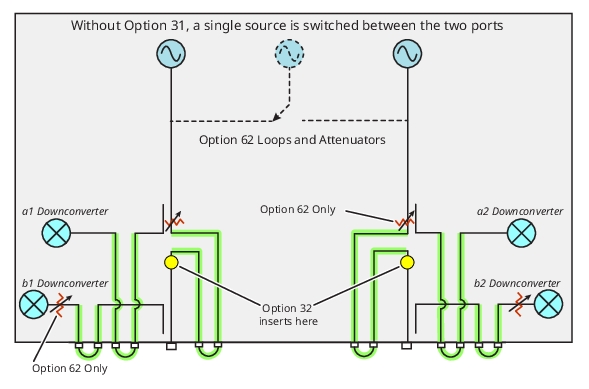
Option 62 and Step Attenuators
The block diagram showing Option 62 is illustrated here. Option 61 includes step attenuators in two positions while Option 62 has step attenuators in four positions as shown. Only front panel loops are shown in this figure, which are for frequencies ≥ 2.5 GHz. The loops for < 2.5 GHz frequency access are located on the rear panel.