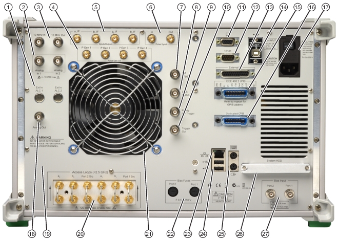
VectorStar MS464xB Series VNA Rear Panel Connectors (1 of 13)
Connector Name | Primary Function / Cross References |
|---|
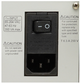
AC Power Connectors and Controls
|
AC Power Input Module | Contains the AC Power Rocker Switch, the AC Power Internal Fuses (under the switch) and the IEC C14 Chassis AC Power Socket, described in rows below. |
AC Power Rocker Switch | Power On Used to the turn the VNA on and off where “|” is ON and “O” is OFF. Standby to Operate Mode Once turned on, the VNA is in standby mode. On the front panel, press and hold the left side Standby/Operate key for at least one (1) second to place the VNA in operate mode. Operate to Standby Mode With the VNA in operate mode, press and hold the
Standby/Operate key for at least one second to return the VNA to standby mode. Power Off Only turn off the VNA when it is in standby mode. Do not disconnect the AC power while the VNA is in operate mode. Do not turn off the VNA while it is in operate mode. |
AC Power Internal Fuses | Use the tab in the AC Power Rocker Switch (described above) to remove the fuse cover and access the fuses. Two (2) T‑Type 6.3 A 250 Volt internal fuses Rated for 700 VA max 90-264 VAC, 47-63 Hz (power factor controlled) |
IEC C14 Chassis AC Power Socket | Allows for a cable connection to AC mains power using the IEC C13 AC Line Socket on the provided power cord. The other end of the provided power cord provides a plug suitable for the instrument location. |
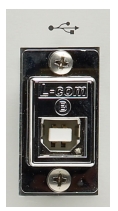
USB Control Port
|
USB Control Port | USB 2.0 Type B Port controlling the instrument externally and for remote operation. |
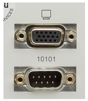
XGA/VGA and Serial (10101) Ports
|
XGA/VGA Video Port | 15-pin Mini D-Sub (f) Connector For simultaneously projecting the instrument’s screen display onto an external VGA monitor, with minimum resolution of 1024 x 768. |
Serial (10101) Port | 9-pin Mini D-Sub (f) Connector Compatible with RS-232C. Provides control for AutoCal modules and other accessories. |
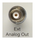
External Analog Out Ports |
External (Ext) Analog Out | BNC (f) Connector External Analog Output. For external attenuator control, external switch control, analog triggering assistance, measurement system integration and other purposes. Normal operating modes: Sawtooth sync sweep, TTL indication of driving port, open loop level controller. Range: -10 V to +10 V; low impedance drive. Accuracy: 20 mV + 2%. |
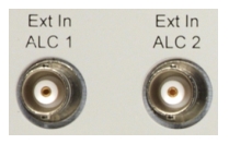
External In ALC Ports |
External (Ext) Automatic Level Control (ALC) | Ext ALC 1 is available with any of Options 53, 80/81/82/83, 86/87. Ext ALC 1 and Ext ALC 2 are both available with Option 31 and any of Options 53, 84/85, 88/89. BNC (f) Connector External Automatic Level Control for both internal signal source generators. |
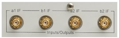
IF Input/Output Loop Connectors
|
Input/Outputs a1 IF | SMA (f) Connectors Inputs used with external converters such as mmWave (mm-W) modules, or for antenna testing. Outputs used with external IF digitizers and processors. Nominal Inputs: 5 to 20 MHz (mode dependent), 0 dBm for full scale Nominal. Outputs: 0.2 to 100 MHz (mode dependent), +10 dBm max These ports also used to interface with the VectorStar ME7838x Broadband/Millimeter Wave Systems. |
Input/Outputs b1 IF | SMA (f) Connectors As above. |
Input/Outputs a2 IF | SMA (f) Connectors As above. |
Input/Outputs b2 IF | SMA (f) Connectors As above. |
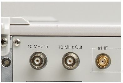
10 MHZ Input/Output Ports
|
10 MHz Input | BNC (f) Connector Auto-sensing, better than 0.001 Hz/Hz accuracy recommended. Signal: –10 dBm to +3 dBm, Nominal 50 Ohms. |
10 MHz Output | BNC (f) Connector Derived from the internal reference time base, unless an external 10 MHz reference input is applied. 0 ± 5 dBm sinusoidal, 50 Ohms |
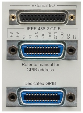
External I/O and GPIB Ports
|
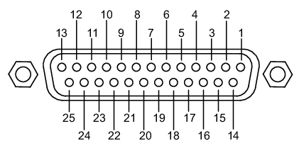
External I/O Port | 25-pin D-Sub (f) connector. User-defined I/O for custom external test set interface, to synchronize with different sweep states, such as Start, Stop, or Driven Port. The next section provides a pin out diagram of the connector. |
External I/O Port Connector Pin Out
|
Pin Number 1 | Limit Pass/Fail – Indicates the results of limit testing for all channels. User selectable from the Limit Line setup menu.
(0 V to 3.3 V) TTL-high = Fail or TTL-low = Fail. |
Pin Numbers 2, 3, 15, 16 | TTL In – Configurable as a digital input for use in sending information to the instrument from external sensors or input devices. The inputs are TTL compatible and 5 V tolerant. |
Pin Numbers 4, 13, 14, 21 | GND – Digital signaling ground. |
Pin Numbers 5 - 12, 17-20, 22 | TTL Out – Configurable as a digital output for use in sending information to external devices, handlers, and output processors. The outputs are 0 V low and +3.3 V high and are TTL compatible. |
Pin Numbers 23 - 25 | Reserved – Reserved for controlling Anritsu external test sets. |
Notes | Pins 17-25 are not available when using a 3739 test set. |
IEEE 488.2 GPIB Port | 24-Pin (f) GPIB Connector GPIB talker/listener port IEEE 488.2 compatible, for controlling the instrument externally, for remote operation. |
Dedicated GPIB Port | 24-Pin (f) GPIB Connector. Dedicated GPIB controller port For the control of external instruments such as power meters, external test sets, or other GPIB compatible accessories. |
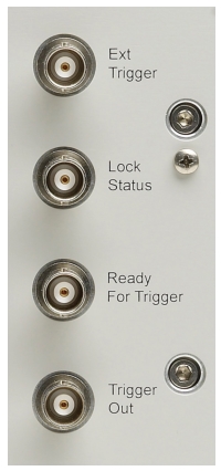
External Trigger and Lock Ports
|
Ext Trigger | BNC (f) Connector External Trigger |
Lock Status | BNC (f) Connector Trigger Lock Status |
Ready for Trigger | BNC (f) Connector |
Trigger Out | BNC (f) Connector |
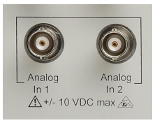
Analog In Ports
|
Analog Input 1 | BNC (f) Connector Independent input for measurements simultaneous with the RF measurements, for current sensing, efficiency computation, and power detection. Range: –10 V to +10 V with automatic offset and gain calibrations. Accuracy: 2 mV + 2% for |V| < 5 V; 2% for |V| > 5 V Nominal input impedance: 60 K Ohms. |
Analog Input 2 | BNC (f) Connector As above. |
Internal System Drive (System HDD) ‘ 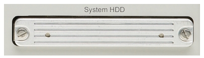 |
System SSD/HDD | The system removable Solid State Drive (or Hard Disk Drive on older VNAs). If spare drives are available, the SSD/HDD can be quickly exchanged for security or other reasons. |
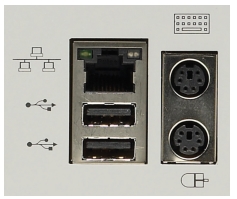
Network, USB, and PS2 Connectors
|
LAN Ethernet Port | 10/100BaseT Ethernet RJ-45 Connector. Standard. |
Universal Series Bus (USB) 2.0 Type A Ports | USB 2.0 Type A Ports, two (2) on Rear Panel. For peripherals such as keyboard, mouse, memory stick, and hardware key. There are two additional USB 2.0 Type A Ports located on the front panel. |
Keyboard/Mouse PS/2 Ports | Dedicated Mini-DIN PS/2 ports, two (2) on Rear Panel. Used to connect a PS/2 keyboard and/or a PS/2 mouse. With a user-supplied PS/2 to USB adapter, can be used to connect a USB keyboard and USB mouse, sparing the USB 2.0 ports for additional peripherals. |
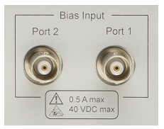
Bias Input Ports
|
Bias Input Port 1 Connector | BNC (f) Connector. One input per Bias Input Port Optional. Equipped with Option 51 or 6x. |
Bias Input Port 2 Connector | BNC (f) Connector. As above. |
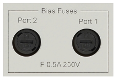
Bias Fuses
|
Bias Fuse Port 1 | Fuse Connector Included with optional Bias Input Ports above. One fuse per Bias Input Port Fuses are F‑Type rated at 0.5 A, 250 V. |
Bias Fuse Port 2 | Fuse Connector As above. |
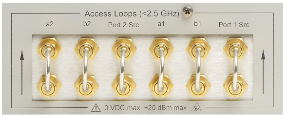
Access Loops (< 2.5 GHz)
|
a2 Access Loop | SMA (f) port with SMA (m) loop.
Optional. Included with Options 51 or 6x. Receiver path for Port 2 For <2.5 GHz frequency coverage. Damage Input Level: +20 dBm max, 0 VDC max |
b2 Access Loop | SMA (f) port with SMA (m) loop.
Optional. Included with Options 51 or 6x. Test receiver path for Port 2. Specifications as above. Also used to connect with the VectorStar MN469xx 4-Port (Multi-Port) Test Sets. |
Port 2 Src Loop | SMA (f) port with SMA (m) loop.
Optional. Included with Options 51 or 6x. Port 2 Source path. Specifications as above. Also used to connect with the VectorStar MN469xx 4-Port (Multi-Port) Test Sets. |
a1 Access Loop | SMA (f) port with SMA (m) loop.
Optional. Included with Options 51 or 6x. Receiver path for Port 1. Specifications as above. |
b1 Access Loop | SMA (f) port with SMA (m) loop.
Optional. Included with Options 51 or 6x. Test receiver path for Port 1. Specifications as above. Also used to connect with the VectorStar MN469xx 4-Port (Multi-Port) Test Sets. |
Port 1 Src Loop | SMA (f) port with SMA (m) loop.
Optional. Included with Options 51 or 6x. Port 1 Source path. Specifications as above. Also used to connect with the VectorStar MN469xx 4-Port (Multi-Port) Test Sets. |
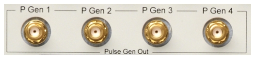
Pulse Generator Outputs |
P Gen 1 P Gen 2 P Gen 3 P Gen 4 | All Pulse Generators, nominal: SMA (f) connectors High: 3.3 V +/- 10% Low: < 1 V Drive Impedance: Low impedance (approximately 50 Ω) Load Impedance: 50 Ω or higher impedance Notes: • Polarity inversion can be set via the PulseView™ configuration dialog. Pulse generator outputs are always active, even when the pulse generators are disabled. • Series load resistance should be kept lower than 10 Ω for typical logic families. |
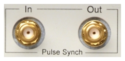
Pulse Synch Inputs and Outputs |
Pulse Synch In | SMA (f) connector Nominal values: High: 3.3 V +/- 10% Low: < 1 V 5.5 VDC damage level 55 ns delay from received synch to T0 (typical) High impedance input |
Pulse Synch Out | SMA (f) connector Nominal values: High: 3.3 V +/- 10% Low: < 1 V < 5 ns delay from T0 to providing an external synch (typical) Drive Impedance: Low impedance (approximately 50 Ω) Load Impedance: 50 Ω or higher impedance Notes: • Pulse Synch Out is always active, even when the pulse generators are disabled. • Series load resistance should be kept lower than 10 Ω for typical logic families. |