 |
|
Status Display | Description | |
|---|---|---|
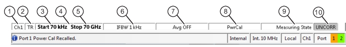
1 | Ch# | Displays the channel number. For example, Ch2 means that the display is for Channel 2. |
2 | TR | Displays the measurement mode as transmission/reflection. |
3 | [Start] Start # Units | In general, the left-side parameters define the starting position of distance, frequency, time, or power. From the FREQUENCY menu, if CW Mode is set to off, displays the current Start Frequency value with units of kHz, MHz, or GHz. |
4 | CW Frequency # Units | From the FREQUENCY menu, if CW Mode is set to on, displays the current CW Frequency value with units of kHz, MHz, or GHz. |
5 | [End] Stop # Units | In general, the right-side parameters define the ending position of distance, frequency, time, or power. From the FREQUENCY menu, if CW Mode is set to off, displays the current Stop Frequency value with units of kHz, MHz, or GHz. |
6 | IFBW | From the AVERAGING menu, reports the IF Bandwidth Frequency setting with units of Hz, kHz, or MHz. |
7 | Avg OFF Avg # # / # | From the AVERAGING menu, reports that Averaging is off, or if values are present, Averaging is on. If Averaging is on, and the Averaging Type is Per-Point, reports the Averaging factor. If Averaging is on, and the Averaging Type is Per-Sweep, the left-side number reports the number of average sweeps; the right-side number displays the Averaging Factor. |
8 | PwrCal | Power Cal indicator appears if a power cal is applied for any port in the channel. |
9 | Measuring State Calibrating State | Indicates whether the instrument is measuring or being calibrated. |
10 | UNCORR | UNCORR (with a dark gray background) indicates that a calibration is not being applied. |
CORR | CORR (with a green background) indicates that the calibration for the active channel is being applied (corrected). | |
EDE | EDE (with green background) Indicates Embedding or De-embedding is being applied. | |
E/O | E/O, O/E, or O/O (with a green background) indicates an optical measurement state. |