|
2.
|
Copy the map file to a USB memory stick and then insert the memory stick into the Anritsu instrument’s USB Type A port. Anritsu recommends copying the map file to the instrument’s internal memory. Refer to Anritsu instrument User Guide.
|
|
A small percentage of USB drives are not fully compatible with Anritsu instruments. Attempting to use one of these at the same time that a MA2700A is also connected to the instrument may disrupt USB communications. The connection may be lost to the drive, the MA2700A, or both. Should this occur, try disconnecting and reconnecting the non-communicative device. For the best performance Anritsu recommends the use of an Anritsu part number 2000-1520-R USB drive.
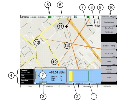
The Status Icons described in Figure: Interference Mapping Overview (1 of 2) show which USB devices are currently connected.
|
|
3.
|
Set the Anritsu instrument to IA mapping and configure the instrument settings.
|
|
4.
|
Load (Recall) the map file from internal memory or from the USB memory stick. Refer to Spectrum Analyzer Measurement Guide.
|
|
5.
|
Connect the MA2700A Handheld Interference Hunter with a directional antenna to the instrument. Refer to Connections, as well as the Spectrum Analyzer Measurement Guide.
|
|
6.
|
Map the interfering signal. Refer to Spectrum Analyzer Measurement Guide.
|
Figure: Interference Mapping Overview (1 of 2) shows an example of interference mapping where the approximate location of the interferer is determined.
 |
|||||
|
|||||
|
Zoom level indication (when using .azm maps). Top is maximum zoomed in position. Bottom is maximum zoomed out position.
|
|||||
|
Current tile location in base map (when using .azm maps). Move the current tile location around the base map using the arrow keys on the Anritsu analyzer.
Note: Panning is not functional when the instrument displayed map is at the maximum zoomed out position.
|
|||||
|
Refer to the Spectrum Analyzer Measurement Guide for detailed information.
|