Remote Spectrum Monitor User Guide : Remote Spectrum Monitors Overview : MS27100A Overview
 
MS27100A Overview
The MS27100A is a remote spectrum monitor designed for OEM applications. This solution can be integrated and branded into a user’s own enclosure or used as a stand-alone monitor is areas where space is minimal. The MS27100A connectors are identified in Figure: Option MS27100A-0406. To set up PC communication with the MS27100A, see Setting Up Communication.
Optional Six-to-One Multiplexer
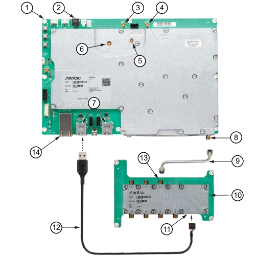
Option MS27100A-0406 enables a USB interface to a 6-port RF multiplexer. This option requires a six-to-one multiplexer (PN: 2000-1894-R) and a USB-A to 5-pin header cable (accessory 3-67367) that connects to the MS27100A Spectrum Monitor Module. The connection interface control is shown in Figure: Option MS27100A-0406.
Option MS27100A-0406
1. MS27100A Module
2. External Power,11.0 to 14.5 VDC, 11 W, 5.5 mm Barrel Connector
3. 10 MHz Reference Output, MCX(f)
4. IF Output, MCX(f)
5. 10 MHz Reference Input, +10 dBm max, +5 VDC max, MCX(f)
6. GPS Antenna Input, MCX(f)
7. USB Type A Connector Input (4)
8. MS27100A RF Input
9. Semi-Rigid Cable
10. Six-to-One Multiplexer (PN: 2000-1894-R)
11. Six-to-One Multiplexer 5 pin Connector Input
12. USB-A Connector to 5-Pin Header Connector Cable (3-63767)
13. Six-to-One Multiplexer RF Output
14. Gbit Ethernet, RJ45 connector
1. Using a torque wrench (PN: 01-201), connect the semi-rigid cable to the RF input of the MS27100A and to the input of the 2000-1894-R.
2. Connect the 3-67367 5-pin header connector to the input connector port of the 2000-1894-R.
3. Connect the 3-67367 USB-A connector to the MS27100A module USB-A port.