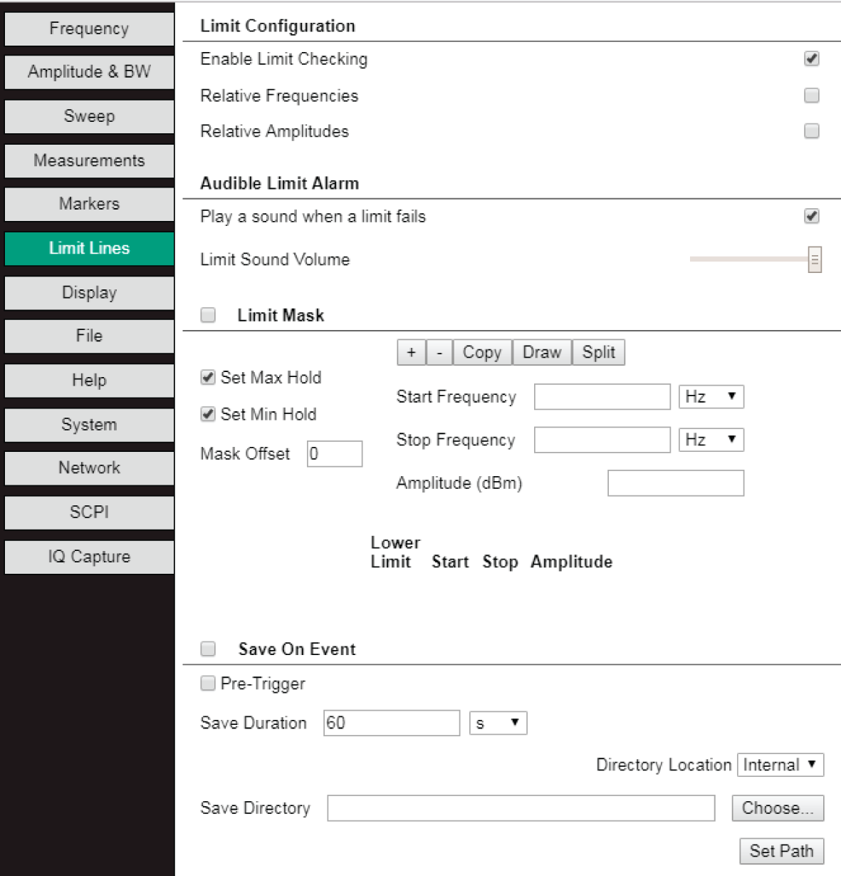
Select the Limit Line tab to create and edit limit lines, limit masks and save on event functions.
Limit Lines Tab
The Limit Line setup panel allows you to create upper and lower limit lines. An unlimited number of limit lines can be created. Limit lines are automatically entered into a table. The active editable limit line is green with larger end circles. The active line can be re-positioned on the measurement display. Place the cursor on the measurement display. Move the cursor and the limit line will move accordingly.
The limit lines shown in the display represent a 'limit being edited' and are not active on the instrument until Enable Limit Checking is checked. Also, editing a limit line will automatically enable limit checking. If Enable Limit Checking is unchecked and the user changes a limit, the box becomes checked.
To create a Limit Mask, click the check box left of the Limit Mask title. Multiple segments will be drawn above and below the trace.
A Limit Sound Volume can be adjusted.
Limit Configuration
• Enable Limit Checking: Click the check box to enable the limit checking feature. A red note will display when a signal amplitude crosses the limit line. If the feature “Play a sound when a limit fails” is checked, a beep will also occur.
• Relative Frequencies: Click to set the values of the start and stop frequencies relative to the center frequency.
• Relative Amplitudes: Click this check box to set the limit line amplitude relative to the top amplitude line value in the display.
Audible Limit Alarm
• Play a sound when a limit fails: When checked, a beep will occur when the limit line is violated.
• Limit Sound Volume: Move the control bar to adjust the volume sound level.
Limit Setup
• Set Max Hold: The signal that violates the upper threshold will trigger to save that trace.
• Set Min Hold: The signal that violates the lower threshold will trigger to save that trace.
• Mask Offset: Sets the a upper and lower mask distance from the trace. Set Mask Offset before clicking the Limit Mask checkbox.
Limit Segments & Mask Buttons
• Add Limit Segment: Press to automatically place a line in the center of the measurement display. The length of the line is 50% of the start and stop frequencies.
• Delete Limit Row: Highlight a limit line in the limit line table. The line will turn green. Press this button to remove it from the measurement display and limit line table.
• Copy: Replicates the active line. A the copied green line will be drawn over the original line. The original line will be colored blue. To get a quick view the new line, change its amplitude. Then drag it to the desired position.
• Draw: Turns the cursor into a pencil. Draws only one segment.
• Split: Halves the highlighted row/line into two segments.
Edit the frequency or amplitude value of the limit line by highlighting the limit line in the limit line table. Then change these values in their entry boxes. After a value has been entered, press the “check” button to use the value or press the “x” button to cancel the entry.
Save On Event
Limit alarm failures are reported whenever a signal is above the upper limit line or below the lower limit line. By using save-on-event, a signal that exceeds the limit alarm can be automatically saved. Click on Enable Limit Checking and Save On Event check boxes to activate Save On Event.
• Pre-Trigger: When checked, the trace before the failed trace and the failed trace will be saved.
• Save Duration: After a fail trigger has occurred, the program will save traces for the time entered. Enter a numerical value or use the up/down arrow buttons to increment/decrement to the desired value. Click the desired unit from the units drop-down list.
• Directory Location: Select Internal or USB if a USB memory device is available.
• Save Directory: Select Choose toenter or navigate to the location where the measurement files are to be saved.
• Set Path: Press when the Directory Location and Save Directory have been entered. Setting this path also sets the Continuous Measurement Saving path.
Note
Note: If a Save On Event is triggered, the next triggered event will take place only after the first event recording is complete.