 |
|
Icon | Description |
Probe 1,2,3: Identifies each receiver. Each receiver label is a button. Click each probe label to display its RMS Status dialog as shown below. The receiver Status dialog provides details of each probe as shown: • Model: The model of the receiver. • Options: The receiver options installed. • Serial #: The serial number of the receiver. • Firmware: The firmware installed. • GPS: Indicates the GPS as GOOD FIX (Strong GPS signal connected). NO FIX (GPS signal is too weak or none found). The receiver coordinates are displayed • Target receiver in use: Flag indicating the receiver is in use and also displays the end-user. In this case the end user is the Simulator. If the receiver is not in use, the flag will indicate – receiver is available for use. 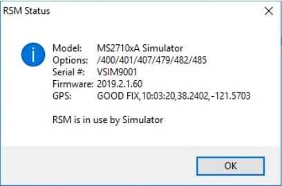 | |
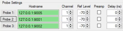
 | Hostname Type in the Host name settings. The URL Hostname is the communication link to the Remote Spectrum Monitors. |
 | Channel Type or select the probe channel. |
 | Ref Level Type or select the receiver Reference Level. |
 | Preamp Select the Preamp check box to activate the Preamp for each probe. |
 | Delay (ns) Type or select a delay time. The delay time selections are in nano seconds. |