In this exercise, you will create a database for three simulated probes located in St. Louis, MO. You need to run the Vision Probe Simulator for this exercise.
Creating the Database
For more description on an entry field, click Help in the bottom left corner of the dialog.
1. On the Start menu, find the folder for Anritsu.
2. Open the sub-folder named Vision Tools and click the Vision Probe Simulator.
3. From the same Vision Tools sub-folder, click the Vision Database Creator. Follow the subsequent steps to create and deploy a Vision database.
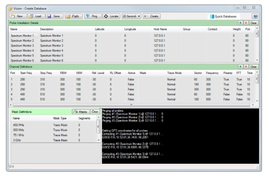
• You will see process information in the black status pane as communication with each probe is verified. If there are any errors, correct them and Ping again. If it is successful, you see a line stating each probe is being ‘pinged’. A number at the end of the line that indicates the time elapsed for a response in milliseconds. Since we are using the Vision Probe Simulator for this exercise, the elapsed time for a response may be zero.
17. Click Locate from the main toolbar.
• This will capture the GPS coordinates of each probe and add that information to the Probe Definition input table. GPS coordinates are assigned randomly, your dBase may not exactly match the coordinates shown here.
18. You need to add a limit line mask. Click Import Masks from the Mask Definition table.
19. Browse to the Example Masks.msk file located in Example Files sub-folder of the Vision Monitor Application Folder (C:\Program Files (x86)\Anritsu Company\Example Files).
• You will now see several masks in the Mask Definition table.
20. In the Channel Definitions table, double-click on the field under the Mask heading.
• This enters Edit mode for the table. Enter 751 MHz in the Mask field for that channel and click Enter.
You need to set the destination folder for the database. The current output destination folder is listed in the status bar. If you want to use the same location as in the last exercise, it should be remembered and listed here. Nothing is required to reuse the same location. If you want to enter a different location, click Path in the main Toolbar and then click a destination folder for this database.
21. Click Create and the database should be created with progress showing in the status pane.
22. Close the Database Creator program.
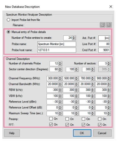
Create Database Dialog – Manual Base Station Entry