 |
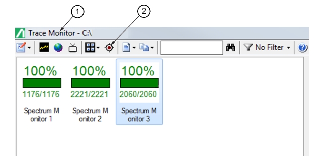
1. Trace Monitor Screen 2. Location Finder Button |
|
1. Trace Monitor Screen 2. Location Finder Button |
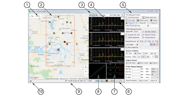 | |
1. Location Finder Map 2. Probe Coordinate Area 3. General Icons 4. Trace Display 5. Settings and Control Panel | 6. Active Button Viewer 7. IQ Linearity Alignment 8. TDOA Signal Correlation 9. GPS Coordinates 10. Map Zoom Button |
Icon | Description |
Spectrum Monitor Spectrum monitors selected on the Base Station and Channel Directory to locate the interfering signal. The short lines that extend out from the square depict the direction of the antenna used. For a view of the interfering signal’s bearing using a single monitor, click the desired monitor represented by a number or star then click 1Probe from the Probe pull-down list above the top trace display. | |
Base Station Base Stations that are close by that can be used to locate the interfering signal. Click on this base station icon to make it one of the three base stations locating the interfering signal. At the same time, the last active number icon base station will turn into a star icon. The trace for the base station will change accordingly in the trace panel. | |
 | Interfering Signal The approximate location of the interfering signal based on the information from the selected base stations. |
Icon | Description |
 | Source Locator Logo Icon This icon is located at the top-left corner of the Source Locator GUI screen. Click to enter the GUI display screen size viewing as shown below. 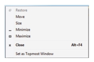 • Restore: Resets the GUI display to the default view. This selection is active only after Maximize has been selected and the GUI screen is in a full screen mode. Restore is normally grayed and only becomes available after Maximize is active. • Move: Move the GUI display screen. • Size: Click a corner of the GUI display and resize the display by dragging the corner. • Minimize: Minimizes the screen to the bottom tray, but the remains active. Click it from the tray to view the GUI display. • Maximize: Expands the GUI screen to full size. • Close: Closes the GUI screen display. • Set as Topmost Window: Sets the Source Locator screen as the lead screen display and can be moved over the other display screens, such as an active Trace Monitor Screen. |
Capture Live Traces From Remote Probes Initially when the Source Locator opens, the last sweep taken is displayed in the trace panels for each of the selected monitors. Click Live to view the trace measurements in real-time. Click again will stop the sweep of the displays. | |
Show Traces from Database This allows you to scroll through both live and database data while looking at location estimates. Live traces in the Locator window do not get stored to the database. This icon button changes state to indicate the active selection: • (Live Data Icon): The two cylinder icon shows that the trace graphs are pulling from the database. • (Stored Data): The TV icon shows the three trace graphs displayed are from live data. | |
Help The Help Icon provides the Help file. | |
Frequency Field Type a marker frequency. Capture Live Traces From Remote Probes must be selected to stop the sweeping, then type a Frequency entry. The display marker will move to selected location. Click Capture Live Traces From Remote Probes to restart the sweep. | |
Collapse Collapse and hides the Settings and Control panel. |