 |
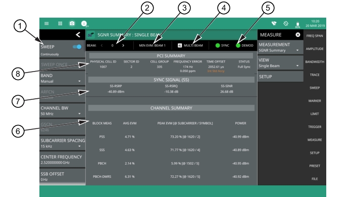
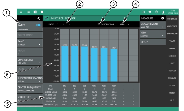
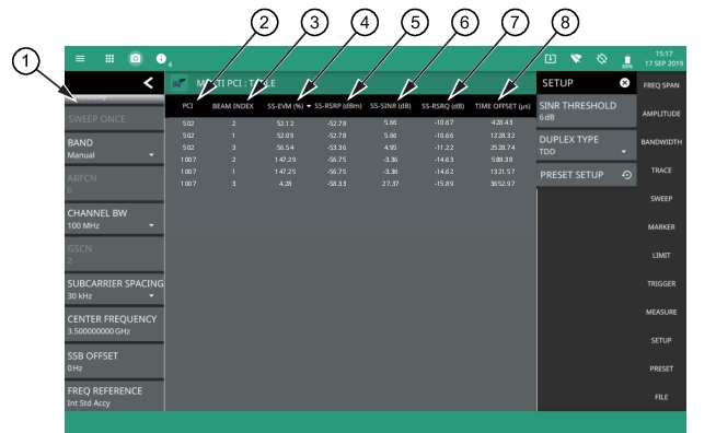
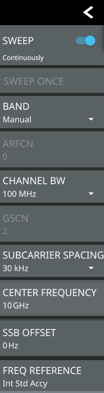
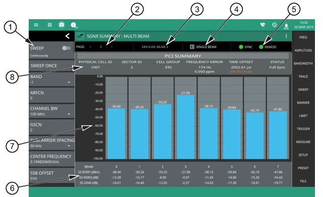
1. 5GNR Analyzer Status Panel: Each measurement features a unique status panel that displays settings and information relevant to the current measurement and view settings. This panel provides quick access to the measurement frequency, subcarrier spacing, channel bandwidth, and band configuration. See Status Panel (5GNR Summary/Multi PCI). 2. PAGE: This field indicates the current multi beam page. A maximum of eight pages (numbered 1 through 8) with eight beams (numbered 0 to 63) on each page can be displayed in multi beam view. You can cycle through the pages using the left/right (</>) arrows or touch the number to select the desired page. 3. MIN EVM BEAM: This field shows which beam measures the lowest error vector magnitude (EVM). 4. SINGLE/MULTI BEAM: This field shows the current view setting. Touch this field to toggle between SINGLE BEAM or MULTI BEAM views. You can also change the view setting from the MEASURE menu. 5. SYNC/DEMOD: Valid 5GNR measurements require the signal synchronization and demodulation. The indicators here blink green when the received signal is synchronized and properly demodulated, indicating that you have a valid measurement. 6. Summary Data: For each beam, the following synchronization signal summary data is displayed: • SS-RSRP: Secondary synchronization signal reference signal received power measured in dBm. • SS-RSRQ: Secondary synchronization signal reference signal received quality measured in dB. • SS-SINR: Secondary synchronization signal-to-noise and interference ratio measured in dB. 7. Beam Display: This area shows the received signal strength of each beam as a vertical bar. The top of the bar is annotated with the maximum signal strength (in dBm). The number of beams displayed depends on how many beams are defined by the band configuration. From 1 to 8 beams can be displayed at once on a page. When more than 8 beams are measured, additional beams can be accessed from additional pages. The beams are numbered from 0 up to 63. If you touch a beam, the view changes to display the selected beam in single beam view. 8. PCI Summary: This area shows the physical cell ID summary data, including the sector ID, cell group number, frequency error, time offset, and sync status. Also noted is the instrument’s reference clock accuracy of Internal, External, or GPS high accuracy (requires GPS). |