![]() |
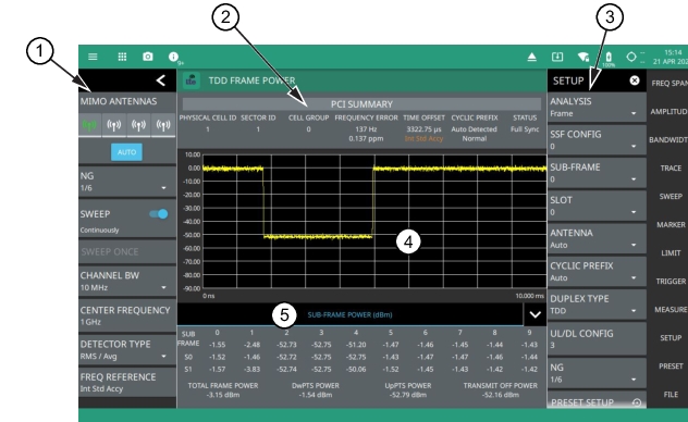
1. LTE Frame Power Status Panel: Each measurement features a unique status panel that displays settings and information relevant to the current measurement and view settings. This panel provides quick access to the measurement frequency and band configuration. See Status Panel (LTE Frame Power). 2. PCI SUMMARY: This area shows the physical cell ID, including the sector ID, cell group number, frequency error, time offset, cyclic prefix, and sync status. Sync status can indicate if there is a PSS or SSS failure, a Full Sync, or an Unknown condition. Also noted is the instrument’s reference clock accuracy of Internal, External, or GPS high accuracy (requires GPS). 3. SETUP Menu: The frame power measurement settings are configured in the SETUP menu. See SETUP Menu (LTE Frame Power). 4. Sub-Frame Power Summary: This area shows the frame power measurement summary data. Power measurements are expressed in dBm. • The power of each subframe, each of two slots in the subframe, and the total frame power is measured. • For TDD duplex type, the downlink pilot time slot (DwPTS), uplink pilot time slot (UpPTS), and transmit off power is measured. (see notes below) |
Note | DwPTS carries reference signals, primary synchronization signal, control information, and data. UpPTS is typically the sounding reference signal transmission from user equipment and is used for the random access channel to setup and synchronize the transmission. |
- ![]() | ANALYSIS Selects the analysis time of full frame, sub-frame, or individual slot. SSF CONFIG Selects the special sub-frame configuration as Auto or one of 10 manual configurations. The slots/sub-frame configuration choices are outlined below: • 0: 3 downlink, 10 guard period, 1 uplink • 1: 9 downlink, 4 guard period, 1 uplink • 2: 0 downlink, 3 guard period, 1 uplink • 3: 11 downlink, 2 guard period, 1 uplink • 4: 12 downlink, 1 guard period, 1 uplink • 5: 3 downlink, 9 guard period, 2 uplink • 6: 9 downlink, 3 guard period, 2 uplink • 7: 10 downlink, 2 guard period, 2 uplink • 8: 11 downlink, 1 guard period, 2 uplink • 9: 6 downlink, 6 guard period, 2 uplink SUB-FRAME Enables limit checking at the specified frequency. The limit test results show as a green PASS or a red FAIL in the measurement table. SLOT Select the measurement method to be PERCENT (%) or X (dB). ANTENNA Sets the MIMO antenna number (0 to 3, or AUTO) to use during a measurement. AUTO will use the antenna with the highest received signal power. CYCLIC PREFIX Sets the cyclic prefix (or guard time interval) to Normal, Extended, or Auto. The cyclic prefix is a duplication of a fraction of the symbol end. This setting affects the OFDM symbol sensitivity to time dispersion. DUPLEX TYPE Selects either frequency division duplex (FDD) or time division duplex (TDD). UL/DL CONFIG Available only in TDD duplex type. Sets the uplink/downlink (UL/DL) configuration, or Frame Format. This selection determines which sub-frames are uplink sub-frames and which are downlink sub-frames, and where the transitions between uplink and downlink sub-frames occur. NG: Selects the NG parameter of 1/6, 1/2, 1, or 2. NG is a parameter that determines the number of PHICH (Physical Hybrid ARQ Indicator Channel) groups in an LTE sub-frame (this number is constant for all sub-frames). PRESET SETUP Presets the SETUP menu to default settings. |
![]() | MIMO ANTENNAS: Toggles the current MIMO antenna setting between AUTO or to select one of the available antennas. When a single antenna is selected, a blue underscore will appear below the antenna icon. The antenna icon is highlighted green when receiving a signal. NG: Selects the NG parameter of 1/6, 1/2, 1, or 2. NG is a parameter that determines the number of PHICH (Physical Hybrid ARQ Indicator Channel) groups in an LTE sub-frame (this number is constant for all sub-frames). SWEEP: Toggles the current sweep setting between continuously or sweep once. SWEEP ONCE When sweep is set to single sweep, SWEEP ONCE updates the measurement display. Data continues to be captured in the background. CHANNEL BW Sets the measurement channel bandwidth. The available bandwidth settings depend on the selected band and bandwidth option installed in the instrument. Refer to Options Settings. CENTER FREQUENCY Sets the center frequency of the measurement channel. DETECTOR TYPE Selects one of three detector types. Several detection methods tailor the function of the instrument to meet specific measurement requirements. There are often more measurement points across the screen than display points. The various detection methods are different ways of dealing with how measurement points will be shown at each display point (see Trace Detector Types). • Peak: This method causes the highest amplitude measurement point to be shown for each display point, assuring that a narrow peak is not missed. • RMS/Avg: In the default case, when the VBW/AVERAGE type is set to Linear, this method detects the average power of measurement points that go into the display point. When VBW/AVERAGE type is set to Log, the traditional average of log (power), such as dBm, is displayed for the detector, as well as for VBW and trace average. • Negative: This method causes the lowest amplitude measurement point to be shown for each display point. This method is also useful when looking at modulated signals, to see if some frequencies are not being used. FREQ REFERENCE Indicates the current frequency reference source of Internal, External, or GPS Hi Accuracy (requires GPS). The instrument automatically selects the frequency reference in the following order of priority: external, GPS, then the internal time base. |