Field Master Pro™ MS2090A User Guide : Real-Time Spectrum Analyzer Measurements (Option 199) : AM/FM Audio Demodulation (Option 24)
 
AM/FM Audio Demodulation (Option 24)
This section describes the MS2090A AM/FM audio demodulation capability (available with Option 24) and key characteristics of analog amplitude modulation (AM) and frequency modulation (FM). The AM/FM analyzer provides the following features:
Ability to listen to audio and sweep trace data simultaneously (Figure: AM/FM Audio Demodulation)
Selectable demodulation frequency with ability to tie frequency to markers.
Demodulation modes:
AM
Upper sideband or lower sideband
Narrowband or wideband FM
Record audio to WAV file
Refer to the previous sections in this chapter for details and menu overviews of general spectrum analysis measurements including setting up frequency and bandwidth parameters, sweep settings, trigger types, attenuator options, and preamp settings. Once the basic measurement is set up, select the AM/FM measurement via MEASURE > MEASUREMENT > AM/FM Audio.
AM/FM Audio Demodulation
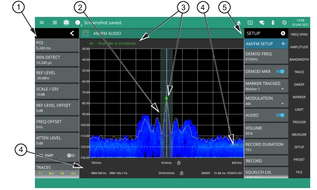
1. The status panel provides quick access to common spectrum analyzer settings. See Status Panel.
2. The trace display area can show multiple traces, each with a unique color. Each trace can be set to Clear/Write, Average, Min or Max Hold, Rolling Average or Rolling Min, or Max Hold. Each trace can have Peak, RMS/Average, or Negative detectors. Traces can be set to Active, Hold/View, or Blank. Refer to Setting Trace and Cursor Parameters. The shaded vertical section marked with green dashed line illustrate the demodulation channel bandwidth.
3. The demodulation marker is the same as a regular marker and can be applied to any trace using the Marker Menu. Refer to Setting Up Markers.
4. The SETUP menu is where the AM/FM demodulation settings are configured. See SETUP Menu (AM/FM Audio).
5. Current frequency, bandwidth, and sweep settings. Refer to Setting Frequency Parameters, Setting Amplitude Parameters, Setting Bandwidth Parameters.
 
MEASUREMENT Menu (AM/FM Demodulation)
The AM/FM measurement SETUP menu is available in MEASURE > MEASUREMENT > AM/FM Audio > SETUP.
MEASUREMENT Menu (AM/FM Demodulation)
 
MEASUREMENT
Selects the current measurement.
VIEW
Only the Normal view is available.
SETUP
IQ CAPTURE
Opens the IQ CAPTURE Menu for capturing or streaming AM/FM IQ data (requires Options 124/125). Refer to IQ Capture/Streaming (Option 124/126 and 125/127) for discussion of IQ Capture and Streaming.
 
SETUP Menu (AM/FM Audio)
The AM/FM audio demodulation SETUP menu is available in MEASURE > MEASUREMENT > AM/FM Audio > SETUP > AM/FM SETUP.
SETUP Menu (AM/FM Demodulation)
 
DEMOD FREQ
Sets the audio demodulation frequency.
DEMOD MKR
Toggles the tracked marker on and sets the demod frequency to track the marker frequency. Use the MARKER Menu to adjust the marker parameters.
MARKER TRACKED
Selects which marker to track. When DEMOD MKR is enabled, the demodulated frequency tracks the indicated marker.
MODULATION
Selects the modulation type to decode. Available modulation types are AM (amplitude modulation), US Band (upper sideband), LS Band (lower sideband), FM Narrow Band, and FM Wide Band.
AUDIO
Toggles the demodulated audio output (sound) on or off. The demodulation frequency must be within the current sweep for audio demodulation. Note that AM/FM audio demodulation cannot be used in conjunction with IQ Streaming or when the IQ streaming output port is set to Data Out.
VOLUME
Sets the audio output volume.
RECORD DURATION
Sets the audio recording time. The maximum recording time is approximately 27 hours, depending on available storage.
RECORD
Starts audio recording. Recorded audio files (.wav) are saved to the Waves folder. Audio will be recorded for the recording duration or will stop when AUDIO is toggled off.
SQUELCH LVL
Sets the RF threshold level for audio playback. This is typically used with weak or intermittent signals to mute the static sound when the signal is below the squelch threshold.
 
Note 
For simultaneous audio demodulation and trace sweep, the set span must not be greater than the maximum capture bandwidth based on the installed bandwidth option (No option: 20 MHz; Option 103: 55 MHz; Option 104: 110 MHz) and the tuning range must not cross more than one internal local oscillator tuning points. These conditions will be indicated by a transient status message at the top of the display.