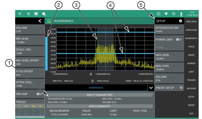
The interference finder measurement is set up using the SETUP Menu (Interference Finder). The interference finder measurement is used in conjunction with a directional antenna to locate the direction of an interfering signal. This test measures the integrated power of a received signal over a specified frequency range. During the measurement, the instrument emits an audio tone that coincides with the power of the received signal. As the antenna is pointed toward the signal source, the signal level increases further into the set MAX and MIN level, and the audio increases in pitch. An example of a frequency modulated interfering signal is shown in the figure below.
Interference Finder Measurement
1. Interference setup parameters and measurement results are shown in a table at the bottom of the display.
2. A vertical bar corresponds to the received signal strength within the integration bandwidth.
3. Dashed vertical lines and a shaded region define the received channel integration bandwidth.
4. Horizontal blue lines define the audio response range for the measurement.
5. All signal power measurement parameters are set via the SETUP menu.
Frequency and level settings for many interfering signals can be set as follows:
1. Press MEASURE on the main menu.
2. Select Interference from the MEASUREMENT button.
3. Press SETUP and then do the following:
• Set the signal INTEGRATION BW (bandwidth).
• Toggle and set the POWER LIMIT if you wish to see pass/fail test results.
• Set the MAX LEVEL and MIN LEVEL for the audio pitch response of the measurement. Note that these settings can also be dragged into position using the indicator bars in the display panel.
• Set the desired volume level. Note that the audio level can also be set from the left side status menu.
Interference Finder is a constant measurement; after it is turned on, it remains on until a different measurement is selected or the sweep is paused. Signal power and a corresponding audio pitch is calculated at the end of each sweep.
Note
Some directional antennas have a narrower null than their forward beam width; therefore, it may be more precise to find the null at the back of the directional antenna to determine the direction of the interfering signal. In this case, you would look for the lowest signal level and the corresponding audio would have the lowest pitch.
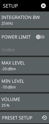
SETUP Menu (Interference Finder)
The interference finder SETUP menu is available in MEASURE > MEASUREMENT > Interference > SETUP. Once the interference measurement is selected, the SETUP menu can be quickly accessed by tapping on the summary display area below the spectrum window.
SETUP Menu (Interference Finder)
INTEGRATION BW
Sets the range of integration used in calculating the received power. The integration bandwidth is displayed as the shaded region between the bandwidth start and stop thresholds (dashed green lines).
POWER LIMIT
The power limit is the threshold value used to determine whether the actual measured channel power will pass or not. If the measured channel power exceeds the set power limit, the channel power test fails; otherwise, the test passes. Pass/fail test results are shown in the measurement results table.
MAX LEVEL
Sets the upper level for the audio response of the measurement. This setting is useful for adjusting the resolution of the tone changes. Power levels above the MAX LEVEL will continue to emit sound an increasingly higher pitch.
MIN LEVEL
Sets the lower level for the audio response of the measurement. The MIN LEVEL also functions as a squelch. Power below this level will not emit a sound.
VOLUME
Sets the volume level for the audio response of the measurement. Note that the master volume can affect the range of this setting. Refer to Interference Finder.
PRESET SETUP
Sets all channel power setup parameters to default. Turns off limits.