 |
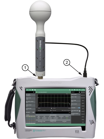
Note | EMF measurements require that an Anritsu EMF isotropic antenna is connected to the analyzer and that the frequency range and span is set within the operating range of the antenna. |
|
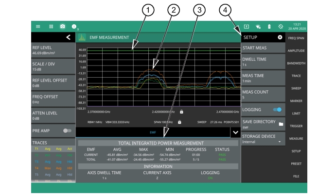 |
1. EMF measurement pass/fail status uses a limit line for the test criteria. You can use either a custom limit line or toggle the International Commission on Non-Ionizing Radiation Protection limit. Either limit supports the same features as in the spectrum analyzer mode. See LIMIT Menu. 2. The trace display area shows traces for the following measurements in units/m2: • Trace 1: Current axis sweep data • Trace 2: Current isotropic result • Trace 3: Average isotropic result • Trace 4: Maximum isotropic result • Trace 5: Total average isotropic result Note that trace detectors, trace averaging, and amplitude units settings are disabled for the EMF measurement. 3. Tabular measurement data shows the current and total EMF measurement results, the current test progress, and the pass/fail status. The information area shows the axis dwell time, the current axis being measured, and the data logging state. 4. The SETUP menu is where the EMF measurement settings are configured. See SETUP Menu (EMF Measurement). |
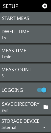 | START MEAS Initiates an EMF measurement. Once the measurement is started, all UI interface is locked until the measurement is complete. A pop-up control appears that allows you to immediately stop the measurement. Note that a valid antenna must be connected and a supported frequency range must be set before a measurement can be started. Note that the START MEAS button also appears on the MEASURE menu and provides the same functionality. DWELL TIME Specifies the time spent on each axis. The sweeps are averaged and saved for further computation. MEAS TIME Sets the duration of each EMF measurement from one minute up to 30 minutes. The default is 6 min. For example, if the axis dwell time is set to 1 s and the measurement time is 1 min, you will get one isotropic result after 3 s and approximately 20 at the end of the one-minute measurement. The CURRENT row in the summary table at the bottom of the screen displays a running average, and the max and min of the computed total integrated power of the isotropic results every 3 s. The displayed values are computed from all measurements completed thus far within the measurement time. At the end of the measurement time, the CURRENT row is cleared and the TOTAL row is updated with the max, min, and running average of all isotropic results (20 in this example). MEAS COUNT Sets the number of EMF measurements to complete from 1 up to 10,000. The EMF test is fully executed when the specified number of measurements have completed. LOGGING Logging is toggled on by default. This must be selected prior to starting the EMF measurement for the results to be logged. Each log file can hold 21 measurements for a maximum of 10,000 measurements total. All files for a measurement run will be stored in the same folder with the year, month, day, measurement time and number. SAVE DIRECTORY Sets the directory of where the log folders are created. STORAGE DEVICE Sets the storage location of either Internal memory or an externally connected storage device. |